Cold cuts
Cold cuts
A new cryogenic cooling milling tool.
Applying a cold gas to reduce the temperature at the tool/workpiece interface and extend tool life or increase machining parameters is an established practice. Walter AG has taken that concept one step further with its Cryo-tec milling tools with two coolant channels, which deliver CO2 and minimum-quantity lubrication compressed air or aerosol emulsion through the machine tool spindle directly to the cutting edge.
The Tübingen, Germany, toolmaker teamed up with Swiss-style machine tool builder Starrag AG to demonstrate and promote the technology. At EMO 2013, the collaborative effort won the MM Award for Innovation for having the most innovative exhibit at the trade fair in the milling category with its production-scale machining of turbine blades using CO2-based cryogenic cooling.
"We cooperated with Starrag because they had the technology for the spindle to work with this kind of media and asked for cutting tools," said Thomas Schaarschmidt, manager of business development–energy for Walter. He added that the toolmaker is open to working with other machine builders that develop alternative spindle technologies to apply CO2 and a second coolant. Cryogenic cooling is also suitable for other machining operations, such as drilling and turning.
Courtesy of Walter USA
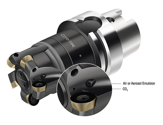
Walter's Cryo-tec cutting tools, such as this modified Model F2334R milling tool, have two channels: one for applying CO2 and one for applying compressed air or an aerosol emulsion.
Schaarschmidt noted the CO2 and lubricant coolant remain separate until they exit the channel ports on the tool body and mix directly at the cutting edge.
The temperature of the liquid CO2 is about 20° C (68° F) as it travels through the spindle and tool and then drops to -78.5° C (-108° F) when it fuses with the ambient air and becomes a gas and dry ice, explained Fabian Hübner, R&D project manager for Walter.
In a test of cryogenic and air-cooled milling vs. dry machining when producing a turbine blade, the former strategy increased the material-removal rate more than 70 percent. The mrr went from 61 cm3/min. (24 cu. in./min.) to 105 cm3/min. (41.3 cu. in./min.), while lowering the tool temperature from 160° C (320° F) to 40° C (104° F) and reducing the cycle time from 4 minutes and 34 seconds to 2 minutes and 40 seconds, according to the company.
Instead of increasing machining parameters, the user can run at the same speeds and feeds and extend tool life, Schaarschmidt added. For example, compared to wet machining, cryogenic cooling reduced flank wear 25 percent when cutting with the same parameters.
Although two channels provide a big advantage over other cryogenic cooling systems, according to Schaarschmidt, work continues on enhancing the Cryo-tec technology. "Walter and Starrag are already testing a three-channel solution in which CO2, aerosol and even [liquid] emulsion can be guided through the spindle," said Walter CEO Mirko Merlo.
That approach enables a machine to supply three media, but only two can be simultaneously applied, Schaarschmidt added. With this approach, the machine tool can switch between various cooling strategies: cryogenic, MQL, cold air combined with any other coolant type and conventional flood lubrication.
The aim is to be able to use the optimal cooling strategy based on the cutting process, explained Dr. Susanne Cordes, the toolmaker's manager of R&D for milling and drilling.
For more information, contact Walter USA LLC, Waukesha, Wis., at (800) 945-5554 or www.walter-tools.com/us. CTE
About the Author: Alan Richter is editor of CTE. Contact him at (847) 714-0175 or [email protected].


