Deep Thoughts
Deep Thoughts
When hole depths exceed four times the drill diameter, problems with cooling and chip evacuation can arise. This article discusses these problems and the drill geometries, machining parameters and coolant options that can minimize them. Charts are included giving speeds and feeds for various workpieces and drill diameters.
Deep-hole drilling got you down? Here are some suggestions for how to avoid the pitfalls and get your operation up to speed.
There is no specific measurement that defines "deep" holes. They can be as shallow as 1/4" or as deep as 20". More useful than trying to come up with an arbitrary point at which holes are called deep is to determine at what point hole depth starts diminishing a twist drill's effectiveness. This is called the "critical depth," the point at which heat and chip accumulation prevent simple twist drills from completing the drilling in one continuous pass of the cutting tool. One rule of thumb states that this depth is around 4 diameters. But exceptions to this rule include drilling free-cutting aluminum or brass workpieces, in which holes 8 to 10 diameters deep can be drilled easily, or, conversely, some automotive forgings in which drilling holes 2 diameters deep can be difficult.
Heat generation usually is the villain in deep-hole drilling operations. It causes cutting-edge failure by reducing drill hardness at elevated temperatures. When drill penetration comes close to critical depth, chips pack the flutes and increase friction to the point of excessive heat buildup. Before critical depth is reached, the twist drill must be retracted (a practice called peck drilling). This allows the tool to cool off and the flutes to be cleared of chips.
Design Variables
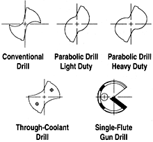
 Figure 1: Cross sections of the five basic types of deep-hole drills. | |
Deep-hole drills come in a variety of styles (the most common, shown in Figure 1, are crankshaft, parabolic-flute, through-coolant, and gundrill), coolant-application options, helix angles, surface treatments, and materials.
The conventional twist-drill flute form, known as the crankshaft form, is the most commonly used deep-hole drill style. Developed to drill the oil holes in crankshafts and engine blocks, this drill is widely used in automotive plants. While considered a deep-hole drill, this type sometimes must be withdrawn to evacuate chips if the hole is extremely deep and/or the workpiece is made of a long-chipping material such as ductile steel or a nonferrous material. Generally, conventional-flute drills can produce holes up to 4 diameters deep.
The parabolic flute form is embodied in two different designs. The general form is a wide flute shape with little or no land present. This style is used for softer materials that generate long chips. The second type of parabolic-flute drill, sometimes referred to as the European style, has a narrower flute and wider lands. This style is designed for harder materials that generate small chips. The parabolic flute forms allow more coolant to reach the point than does the conventional flute form. And because the parabolic flutes provide more room for chips, parabolic drills also remove a greater volume of chips without clogging. Both parabolic styles can drill to depths of 10 to 15 diameters in one pass, depending on workpiece material and drill diameter. (Smaller diameter drills are relegated to smaller depth-to-diameter ratios.)
Another form of deep-hole drill is the gundrill, which, at least in relation to its diameter, drills the deepest holes of any tool. Typically, gundrills are of single-flute design, though 2-flute designs are available. They are usually made from carbide brazed or welded onto a crimped tube. The tube introduces coolant to the carbide head to push chips back out through the hole being drilled. Because of the crimped tube's light construction, gundrills are fed at very light feed rates (about 0.0002 ipr), which generate fine chips.
Through-coolant drills are available in both conventional and parabolic flute forms. The direct flow of coolant from the drillpoint to the point of cut cools the drill, an important benefit in deep-hole applications, and thus extends tool life. Also, the coolant flow pushes the chips back up the flute and reduces the chance of flute clogging. These benefits allow a coolant-fed conventional drill to go 7 to 10 diameters deep without requiring withdrawal, compared to a non-through-coolant conventional drill's 4-diameter maximum. A parabolic through-coolant drill can drill 15 to 17 diameters deep, compared to a non-through-coolant parabolic's 10- to 15-diameter maximum.
When coolant-fed drills aren't available, flood cooling is an effective way to dissipate heat when the drill is being retracted from the hole. This will prevent heat buildup in the tool, which can soften cutting edges and shorten tool life. In flood applications, coolant doesn't need to be particularly lubricious in a deep-hole operation, because very little fluid actually reaches the cutting edges once the hole is initiated.
Along with proper coolant application, high helix angles increase the drill's ability to eject chips from the hole, thereby decreasing the opportunity for hot chips to transfer heat to the drillpoint. A higher helix also produces higher rake angles along the drill's cutting lips. Those higher rake angles translate into reduced energy generated along the cutting edge.
Surface treatments or coatings are recommended as a way to reduce the friction generated between the chip and the drill flute as hole depth increases. Lower friction means lower temperatures and therefore less opportunity for chip welding and flute clogging to occur. Surface treatments of deep-hole-drill substrates range from simple technologies such as steam oxide or nitride to more complex TiN or TiCN coatings.
In general, the drill's substrate material doesn't affect the way a drill removes chips, but it does affect tool performance in terms of wear mechanisms and heat buildup caused by worn cutting edges. Substrate materials such as M-1, M-2, M-7, and M-10 HSS work well on workpiece materials softer than Rc 30. Drills made from high-cobalt M-35 or M-42 HSS should be used on materials harder than Rc 30, as well as on stainless steels and high-temperature alloys. Cobalt-HSS drills should also be considered for long production runs involving softer workpiece materials. Solid-carbide or carbide-tipped drills offer higher wear resistance, but setups must be very rigid to take advantage of this property.
In terms of geometry, the deep-hole drill you choose should adhere to these specifications:
- The helix angle should be around 38° to allow chips to flow efficiently up the drill flutes. However, for workpiece materials such as bronze, brass, or high-temperature alloys, a lower helix angle may be more effective.
- A web thickness of 35% to 45% of the drill diameter will maintain drill rigidity when using extra-long drills. The web is normally constant for the specific length of the flute (normally 1/3 of the flute length), then increases at a predetermined rate, depending on the drill and the workpiece material. This allows chips to exit the point/material interface with no restrictions.
- Because the web is so thick, it must be thinned in some fashion. This thinning will reduce the pressure required to penetrate and eliminate or decrease walking of the drillpoint at penetration.
The most common way to thin a web is to grind a standard split point in either 118° or 135° point angles. Another point angle gaining popularity is the spiral point, which, when coupled with the higher feed rates used in deep-hole drilling, will sometimes, depending upon the workpiece material, generate a smoother hole finish than the standard chisel-point drill.
Parameters
| ||||||||||||||||||||||||||||||||||||||||||||||||||||||||
| Table 1: Suggested speeds for various workpiece materials. | ||||||||||||||||||||||||||||||||||||||||||||||||||||||||
Once you've selected the optimum drill for your operation, make sure to select the proper parameters, including speeds, feeds, positioning, and alignment. Table 1 lists recommended speeds for various workpiece materials.
Feed rates play a key role in determining the success or failure of a deep-hole drilling operation. A feed rate that's too slow generates fine chips that are difficult to eject. Conversely, feed rates that are too fast can cause the drill to bend or spring, starting an immediate deviation from a straight line. The problem of springing is of particular concern when using small-diameter drills. Table 2 lists recommended feed rates for various drill diameters.
The position of the drill (conventional or inverted) seems to have little effect except in situations when one must use a drill with a helix angle lower than 38°. Flute clogging due to poor chip ejection becomes a problem when using a lower helix drill in the conventional drilling position. Better chip removal is achieved by drilling in an inverted position, which allows chips to fall freely from the hole due to gravity, thereby reducing the chance for heat transfer from the chips to the drill. However, when using a high-helix drill, drilling in a conventional position is preferred, because higher-helix flutes tend to impede the free falling of chips.
| |||||||||||||||
| Table 2: Suggested feed ranges for various drill diameters. | |||||||||||||||
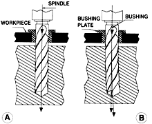
The relative effects of alignment and misalignment of the spindle, drill, and drill bushing are shown in Figure 2. While the misalignment indicated in B is somewhat exaggerated, the results would be the same if the misalignment amounted to only 0.001" to 0.002". Starting out of line, the hole would deviate from a straight line and result in a curved hole. The deeper the hole, the greater the deviation from the true axis. The same conditions would result from too much play between the drill and the bushing guide, or from excessive pressure that would cause the drill to spring.
 Figure 2: The effects of good alignment of spindle, drill, and drill bushing (A) and misalignment of these components (B). | |
For deep holes, a bushing usually is needed to counteract the penetration forces and prevent walking when the tool first enters the workpiece. The bushing's centerline must be aligned precisely with the spindle's centerline. If the overall drill length is enough to cause excessive side deflection or bending of the drill body during initial penetration of the drillpoint, the use of an additional support bushing, or whip, is necessary. The length at which a whip becomes necessary depends on several variables, and must be determined by trial-and-error.
There are many potential pitfalls when drilling deep holes. But by paying close attention to the drill, the workpiece, the parameters you're using, and the ways all three interact, deep-hole drilling needn't be a headache.
About the Author
Raymond Moring, CmfgE, is a product specialist with Greenfield Industries Inc., Augusta, GA.


