The difficulties of tapping

Author Christopher Tate
Published
May 06, 2019 - 03:30pm

My machining career started at our family machine shop. When I began, we had only conventional, or manual, machine tools. Bridgeports from the 1960s, a Monarch 10EE toolroom lathe built in 1946 and a Lodge & Shipley lathe with a placard announcing that it conformed to the specifications of the War Production Board from World War II were some of the machines I used while learning the craft.

I learned how to tap holes by hand with a tap wrench and tap block. Sometimes, I would “power tap” with the Bridgeport or use the tailstock of a lathe. Other times, I employed methods that even the saltiest of machinists might question, like using a ½"-dia. drill motor to make threads in large castings.

Rarely having any trouble, it is fair to say I was adept at tapping holes. However, when our first CNC machine tool arrived in 1995, tapping became the bane of my existence. Broken taps, bad surface finishes, oversized holes and scrapped parts quickly were the norm. It was as if I had forgotten how to tap holes.
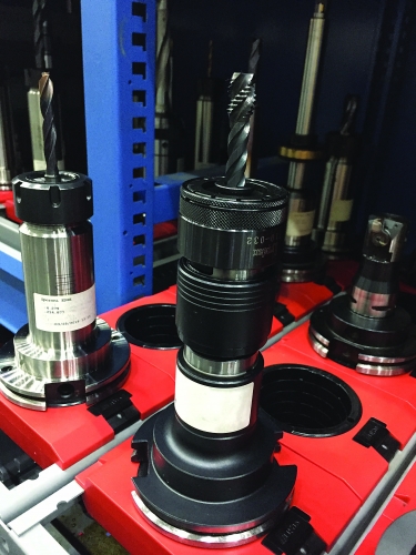
Mitsubishi Hitachi Power Systems Americas has the rigid tapping option on its controls but uses tension compression holders to give another level of protection from errors. Photo credit: Christopher Tate
Mitsubishi Hitachi Power Systems Americas has the rigid tapping option on its controls but uses tension compression holders like this one to give another level of protection from errors in programming or setup. Image courtesy of C. Tate

After research and consultation with experts, along with practice on the machine, I realized I had to change my approach. Tapping methods used on conventional machines were not going to work on the machining center.

Sensory Focus

When tapping on a conventional machine, a machinist constantly adjusts to sights and sounds, and this ability to closely interact with the tapping operation allows a lot of leeway in tap selection. With conventional machines, it was common for us to apply inexpensive hand taps for everything, including power tapping. Tapping on a machining center prevents a machinist from being actively engaged in the process and removes the ability to use his senses for guidance while the tap is in the hole. 

With a machining center, a machinist can’t stop in the middle of a tapping operation when something sounds or feels wrong. You know that something is incorrect only after a tap is broken or threads are bad. Having the correct tap geometry is critical when tapping on a machining center. There is no time to react to a poor situation caused by using the wrong tool. I learned fast that taps have features designed for specific applications. Using a tap in an application for which it was not designed yielded lousy results and frustration.

Holding and driving taps on conventional machines was done using collets, drill chucks, tap wrenches (held by hand) and, in the crudest setups, adjustable wrenches.

When I purchased the machining center, I bought the rigid tapping option, which is intended to eliminate the need for special toolholders. So I tried to hold tools on the machining center like I had on conventional machines. I was met with frustrating results. My first attempt used a 3-jaw keyed drill chuck. After failing to thread a hole with a
3⁄8-16 tap on three consecutive tries, I knew that other methods were needed. 
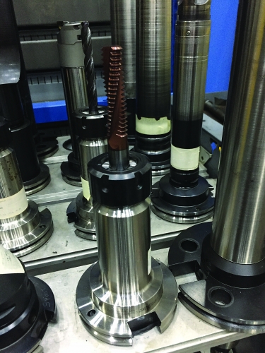
Thread milling is the first choice for threadmaking at Mitsubishi Hitachi Power Systems Americas. Photo credit: Christopher Tate
Thread milling is the first choice for threadmaking at Mitsubishi Hitachi Power Systems Americas. Making threads that have a large depth-to-diameter ratio can be much easier with a thread mill than with a tap. Image courtesy of C. Tate

The second setup incorporated a standard double-angle collet, which worked much better until the tap started to wear, increasing cutting forces to the point that the tap began to slip in the collet. The result was poor thread quality and a grimace as I wondered how much of the tap was going to exit the hole. I tried a few other methods and finally found relief when my tap salesman suggested I use a tension compression holder.

Tension compression holders are spring-loaded and allow axial movement of the tap, which mitigates undesirable effects associated with tap movement. These holders also are designed specifically for holding taps, so they don’t have issues with movement in the collet. Technically, a tension compression holder is not needed for rigid tapping. However, the holder does protect against small inaccuracies in the system. Because the holders are easy to use and one size accepts a variety of tap sizes, I started using them all the time.

Lubricious Threading

Tapping on any machine tool requires some type of lubricant or cutting fluid. On conventional machines, I used various waxes, cutting fluids and oils made especially for threading. I could have used the same methodology for the machining center, but it is not practical to stop the machine midcycle and apply oil to the tap or hole. Also, the petroleum-based products floating around in the coolant caused other issues, and tapping with water-soluble coolants is normal practice anyway.

It did not take long to realize that tapping operations are sensitive to coolants. I ran the machine for several months using a coolant that worked well with general milling and drilling, but when I tried tapping 6-32 threads in aluminum, I experienced sporadic results. Thread quality was poor, and I could not trace the problem to the tap, tapholder or machine. After tapping a few dozen holds with old-fashioned tapping oil, I figured out that the coolant did not provide the necessary lubricity. I ended up changing brands and carefully monitoring the concentration each day, which eliminated the problem. Getting high-quality threads requires not only getting coolant to the hole but having the proper formulation and concentration.

I learned many lessons about tapping, but the most valuable lesson was how to thread mill. Thread milling can be a far better way to thread holes than tapping. I became familiar with thread milling at a trade show. I tried thread milling on my machines, and now I reach for the thread mill before the tap. With thread milling, I do not need to reverse the spindle. There are typically no coolant or toolholder issues. And broken thread mills do not usually stay stuck in holes like broken taps.

Tapping is one of the most difficult machining operations to master. Many variables, such as tap geometries, tap coatings, cutting fluids, cutting speeds and toolholders, play significant roles in success. Working with an applications engineer at a good tap manufacturer is the best way to correctly set all the key variables.    


Related Glossary Terms

  • chuck

    chuck

    Workholding device that affixes to a mill, lathe or drill-press spindle. It holds a tool or workpiece by one end, allowing it to be rotated. May also be fitted to the machine table to hold a workpiece. Two or more adjustable jaws actually hold the tool or part. May be actuated manually, pneumatically, hydraulically or electrically. See collet.

  • collet

    collet

    Flexible-sided device that secures a tool or workpiece. Similar in function to a chuck, but can accommodate only a narrow size range. Typically provides greater gripping force and precision than a chuck. See chuck.

  • computer numerical control ( CNC)

    computer numerical control ( CNC)

    Microprocessor-based controller dedicated to a machine tool that permits the creation or modification of parts. Programmed numerical control activates the machine’s servos and spindle drives and controls the various machining operations. See DNC, direct numerical control; NC, numerical control.

  • coolant

    coolant

    Fluid that reduces temperature buildup at the tool/workpiece interface during machining. Normally takes the form of a liquid such as soluble or chemical mixtures (semisynthetic, synthetic) but can be pressurized air or other gas. Because of water’s ability to absorb great quantities of heat, it is widely used as a coolant and vehicle for various cutting compounds, with the water-to-compound ratio varying with the machining task. See cutting fluid; semisynthetic cutting fluid; soluble-oil cutting fluid; synthetic cutting fluid.

  • cutting fluid

    cutting fluid

    Liquid used to improve workpiece machinability, enhance tool life, flush out chips and machining debris, and cool the workpiece and tool. Three basic types are: straight oils; soluble oils, which emulsify in water; and synthetic fluids, which are water-based chemical solutions having no oil. See coolant; semisynthetic cutting fluid; soluble-oil cutting fluid; synthetic cutting fluid.

  • depth-to-diameter ratio

    depth-to-diameter ratio

    Ratio of the depth of a hole compared to the diameter of the tool used to make the hole.

  • gang cutting ( milling)

    gang cutting ( milling)

    Machining with several cutters mounted on a single arbor, generally for simultaneous cutting.

  • lathe

    lathe

    Turning machine capable of sawing, milling, grinding, gear-cutting, drilling, reaming, boring, threading, facing, chamfering, grooving, knurling, spinning, parting, necking, taper-cutting, and cam- and eccentric-cutting, as well as step- and straight-turning. Comes in a variety of forms, ranging from manual to semiautomatic to fully automatic, with major types being engine lathes, turning and contouring lathes, turret lathes and numerical-control lathes. The engine lathe consists of a headstock and spindle, tailstock, bed, carriage (complete with apron) and cross slides. Features include gear- (speed) and feed-selector levers, toolpost, compound rest, lead screw and reversing lead screw, threading dial and rapid-traverse lever. Special lathe types include through-the-spindle, camshaft and crankshaft, brake drum and rotor, spinning and gun-barrel machines. Toolroom and bench lathes are used for precision work; the former for tool-and-die work and similar tasks, the latter for small workpieces (instruments, watches), normally without a power feed. Models are typically designated according to their “swing,” or the largest-diameter workpiece that can be rotated; bed length, or the distance between centers; and horsepower generated. See turning machine.

  • lubricity

    lubricity

    Measure of the relative efficiency with which a cutting fluid or lubricant reduces friction between surfaces.

  • machining center

    machining center

    CNC machine tool capable of drilling, reaming, tapping, milling and boring. Normally comes with an automatic toolchanger. See automatic toolchanger.

  • milling

    milling

    Machining operation in which metal or other material is removed by applying power to a rotating cutter. In vertical milling, the cutting tool is mounted vertically on the spindle. In horizontal milling, the cutting tool is mounted horizontally, either directly on the spindle or on an arbor. Horizontal milling is further broken down into conventional milling, where the cutter rotates opposite the direction of feed, or “up” into the workpiece; and climb milling, where the cutter rotates in the direction of feed, or “down” into the workpiece. Milling operations include plane or surface milling, endmilling, facemilling, angle milling, form milling and profiling.

  • milling machine ( mill)

    milling machine ( mill)

    Runs endmills and arbor-mounted milling cutters. Features include a head with a spindle that drives the cutters; a column, knee and table that provide motion in the three Cartesian axes; and a base that supports the components and houses the cutting-fluid pump and reservoir. The work is mounted on the table and fed into the rotating cutter or endmill to accomplish the milling steps; vertical milling machines also feed endmills into the work by means of a spindle-mounted quill. Models range from small manual machines to big bed-type and duplex mills. All take one of three basic forms: vertical, horizontal or convertible horizontal/vertical. Vertical machines may be knee-type (the table is mounted on a knee that can be elevated) or bed-type (the table is securely supported and only moves horizontally). In general, horizontal machines are bigger and more powerful, while vertical machines are lighter but more versatile and easier to set up and operate.

  • relief

    relief

    Space provided behind the cutting edges to prevent rubbing. Sometimes called primary relief. Secondary relief provides additional space behind primary relief. Relief on end teeth is axial relief; relief on side teeth is peripheral relief.

  • tap

    tap

    Cylindrical tool that cuts internal threads and has flutes to remove chips and carry tapping fluid to the point of cut. Normally used on a drill press or tapping machine but also may be operated manually. See tapping.

  • tapping

    tapping

    Machining operation in which a tap, with teeth on its periphery, cuts internal threads in a predrilled hole having a smaller diameter than the tap diameter. Threads are formed by a combined rotary and axial-relative motion between tap and workpiece. See tap.

  • threading

    threading

    Process of both external (e.g., thread milling) and internal (e.g., tapping, thread milling) cutting, turning and rolling of threads into particular material. Standardized specifications are available to determine the desired results of the threading process. Numerous thread-series designations are written for specific applications. Threading often is performed on a lathe. Specifications such as thread height are critical in determining the strength of the threads. The material used is taken into consideration in determining the expected results of any particular application for that threaded piece. In external threading, a calculated depth is required as well as a particular angle to the cut. To perform internal threading, the exact diameter to bore the hole is critical before threading. The threads are distinguished from one another by the amount of tolerance and/or allowance that is specified. See turning.

  • toolholder

    toolholder

    Secures a cutting tool during a machining operation. Basic types include block, cartridge, chuck, collet, fixed, modular, quick-change and rotating.

  • toolroom lathe

    toolroom lathe

    High-precision lathe built to hold tighter tolerances than regular, general-purpose lathes can hold. See lathe; turning machine.