For Good Measure
For Good Measure
Software-based video tool inspection systems can read tool geometries much more precisely than other measurement systems. This article looks at the technology behind these systems and explains how this technology detects and measures tool edges and angles.
Take a look at how software-based video inspection systems meet the challenge of achieving more precise measurements of cutting tools.
For years, the optical comparator was the most commonly used device for tool inspection. The comparator offered reasonably priced technology for checking tools by profile projection. The use of surface illumination, digital readout, and edge finding further enhanced the device. However, the comparator lacked the ability of the naked eye or digital camera to see fine detail in the geometry of cutting tools. The toolmakers' microscope, with its linear scales and digital readout, was an improvement over the comparator, because tool images could be clearly seen and measured. But like the comparator, the toolmakers' microscope was still a mechanical system limited to hardware upgrades.
Like a comparator or microscope, a digital system uses ground glass lenses to magnify features on a tool. However, this type of system also uses a camera to convert the tool image to a digital image. Table 1 compares the features of various optical and digital systems used for the inspection of cutting tools.
Early versions of monitor-based video inspection systems used black-and-white cameras, television monitors, and line generators. Measurements were made by linear scales and digital readout or by a pixel count from the monitor screen. In a video system, the number of pixels, or single dots on the monitor screen, determines the display resolution. With pixel count, cutting tools can be easily measured. And because tool images are in a digital format, they can be printed, but they lack supporting documentation such as x-axis, y-axis, and rotational measurements.
In the past five years, the lower cost and higher sophistication of computers, video imaging cards (frame grabbers), and cameras have boosted the popularity and accuracy of video inspection systems. System manufacturers can use frame grabbers to display live tool images on a computer monitor screen and write custom programs that increase the speed and accuracy of video inspection.
System Features
Any software written for tool inspection must consider not only what job needs to be done (measurement of lengths, diameters, or angles), but also the environment in which it will be used and the backgrounds of the people who are likely to use it. Ideally, the software should be self-explanatory and simple enough for a first-time computer user to start the inspection process immediately. Software-based systems currently exist for inspection of workpiece surfaces, which tend to be in flat planes where focus and reflection of light can be controlled more easily. The inspection of cutting tools, however, presents unique problems in that tool surfaces are not usually in the same x-, y-, and z-planes. In addition, most tool surfaces are curved and have a fine finish, which makes them very reflective.
Software has now been developed exclusively for the inspection and documentation of cutting tools. Written in Windows format, the software has pull-down menus with instructions for system setup, tool measurement by calculation or comparison, tool documentation, data collection, image saving and retrieval, notes storage, and help files. The menu shown in Figure 1 allows the user to select setup functions such as inch or metric measurement, crosshair color, crosshair rotational measurement, and crosshair style (solid line or dashed line).
Actual calculations of angles, diameters, and lengths on cutting tools are typically made on optical and digital systems by moving the stage or lens to place a crosshair at a given location. Measurements are then displayed on a digital readout. Digital systems, with or without a computer, have the ability to measure by counting pixels on the monitor screen. The operator places a small crosshair line on the edges to be measured (Figure 2), and the system counts the number of pixels between the lines or points. With the aid of PC software, these point locations can then be used in custom programs to calculate distances, clearance or cutting angles and radii, land widths, and helical angles.
Although measuring by pixel count is fast and easy, accuracy is dependent on the fixed pixel size of the monitor. Accuracy is also directly proportional to magnification. A pixel cannot be divided into parts. On a typical 0.28mm dot pixel Super VGA monitor, the pixel size is 0.011". At zero magnification, it takes 90 rows of pixels to equal 1", whereas at 105 magnification, it takes 900 rows to equal 1". A simple rule of thumb: The higher the magnification, the better the resolution. More pixels allow the operator to see finer detail and make more accurate measurements.
Inspection Methods
Software-based inspection systems also have the ability to find edges on tools. However, the edge-finding method used by these systems is dramatically different from that used by optical comparators. On a comparator, light shines through a fiber-optic cable; the device finds an edge when the light beam is broken. In a digital imaging software system, however, edges are indicated by sharp changes in gray tone in a black-and-white system or color tone in a color system.
Another typical inspection method is a comparison or overlay. The actual tool feature is checked against an overlay of exact size and tolerance for a quick visual go/no-go check. An overlay for an optical comparator is drawn on transparent paper. Through special computer software programs, the operator can use the keyboard to enter values to create an overlay on the computer monitor (Figure 3). Rather than calculating an exact value for a particular tool feature, the operator simply ensures that it is within the tolerance allowed. Angles, circles, or radii can be checked, and custom programs can be written for go/no-go checks.
An example of a typical custom program would be the inspection of a corner radius on a helical endmill (Figure 4). Here, radii are drawn tangent to vertical and horizontal lines representing the outer diameter and front face of the endmill. The endmill is then turned, rolling the corner radius through the computer-generated radii for a quick go/no-go check.
Documentation
A major benefit of computer software systems is inspection documentation. All tool manufacturers are becoming keenly aware that proper quality documentation is a requirement of ISO 9000 certification. This documentation includes measurements of all critical tool features and records of notes and corrective actions. Inspection software provides additional documentation: a retained image of the tool or feature to be measured.
The ability to save an image with all of its documentation on a hard drive or diskette is a valuable asset. Saving the image allows the operator or inspector to recheck dimensional features after the tool is no longer available. Print functions allow the inspection data and image to be printed or transferred by modem to other locations using similar software. If the system is in a network of PCs, the image is accessible not only to the tooling inspector, but also to engineers, managers, sales personnel, and end users.
Because each color image occupies 320,000 bytes in a computer hard drive, it is not practical to save an image of every tool made. Instead, critical data on a sampling of tools can be collected by downloading to an external SPC data collector. Data can also be collected on a spreadsheet that is integrated into the inspection system (Figure 5). With the spreadsheet open, the operator can use the mouse to transfer data into an internal SPC program. This completely paperless process eliminates operator-translation errors. In addition, running on a PC eliminates the need for external data collectors and the use of confusing serial interfaces for data transmission.
Some digital software systems offer the possibility of using the tool image as the background for a CAD system or reverse engineering. For a tool with no documentation, the operator can trace the outline of the tool to its exact detail, scaled to the CAD program. Tool drawings can be saved in a data exchange format for future use, or they can be used to draw tolerance zones for custom electronic overlays.
Looking Ahead
The future for software-based video inspection systems promises many improvements. With the arrival of Windows 95, software programs can be run at faster speeds. Besides the ability to save file names longer than eight characters, Windows 95 can run several programs simultaneously, such as inspection, printing, SPC, and CAD programs.
New video cards are available that have higher resolution capabilities, faster transmission times, and higher refresh rates (frequency at which the screen's horizontal lines are recharged). Current single-chip and three-chip cameras offer resolutions from the standard 300 scan lines to 2,000 scan lines. Three-chip cameras offer better image quality with less bleeding between colors. However, for increased resolution to be used effectively, the camera, frame grabber, and monitor must have the same capacity. While these enhancements to standard systems come at a price, they offer superior clarity and resolution.
The advent of digital imaging hardware and software makes it possible for a small or medium-size quality-conscious shop to enjoy the latest cutting tool inspection technology without having to purchase a total hardware system. Upgrading an inspection system can be as simple as loading a new program diskette. By investing in inspection software, a shop is assured of maintaining an up-to-date inspection system well into the future.
|
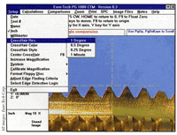 Figure 1: Setup menu of Euro-Tech Corp.'s Cutting Tool Measurement software. |
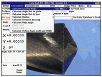 Figure 2: Angle calculation by pixel count. |
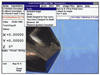 Figure 3: Comparison menu for a go/no-go check. |
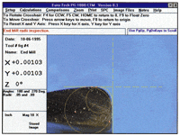 Figure 4: Program for inspection of a corner radius. |
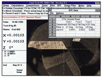 Figure 5: SPC spreadsheet. |
About the Authors
Michael Smith and Jerry Kowalsky are co-owners of Euro-Tech Corp., Brookfield, Wis.


