Improving the Threading Process

Author CTE Staff
Published
May 21, 2024 - 03:30pm

Whether it’s cutting tool life, price, performance, or equipment obsolescence, job shops have a host of challenges they must overcome, said Tracy Hebert, Application Engineer for Janesville, Wisconsin-based Vargus USA. Hebert’s territory covers Texas, Louisiana and Mississippi.

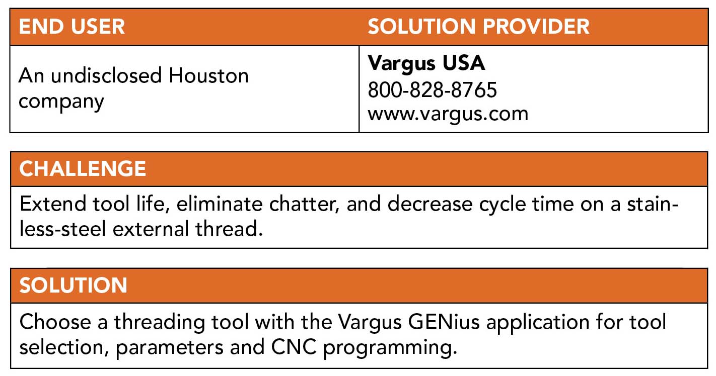
An undisclosed shop in Houston, for example, required assistance to improve tool life while eliminating an occasional chatter problem when threading a thin wall 316L stainless steel seamless tube, he said. The part had a 4.00" diameter with 8" pitch NPT threads and was produced on a Puma 400 CNC lathe with a Fanuc control. After producing five to six parts, the machinist had to index the insert to a fresh corner.
Solution

To help improve the process, Hebert said he showed the shop supervisor the Vargus GENius application for tool selection, parameters and CNC programming. (The Vargus GENius app can be found at Vargus.com or downloaded from the app store on any iPhone or Android smartphone.) Hebert walked the supervisor through the application process, initially indicating the part requirements: a right-hand thread externally threaded toward the chuck with an 8" pitch NPT, one start and a 4.00" nominal size. In addition, M13 was selected as the material class because 316L stainless falls under that classification.

With this information, GENius offered 231 options, Hebert noted. The GENius can then be filtered down to the best tooling for the application. The machine requires a toolholder with a 1.25" square shank, which Hebert selected in the app filter. That information reduced the number of options to 26. The AL125-3 option was chosen, with the app indicating to use a YE3-1N anvil. Next, they selected the Vargus 3FSER8NPT-FST TiAlN-coated insert with a 3/8" inscribed circle, from the Vargus FS line of fully sintered inserts.

The Vargus GENius app helped improve insert life, eliminated chatter and decreased cycle time, when producing external threads in 316L stainless steel parts.
The Vargus GENius app helped improve insert life, eliminated chatter and decreased cycle time, when producing external threads in 316L stainless steel parts. Image courtesy of Vargus USA

For infeed, the shop supervisor selected the radial infeed method, Hebert said. In addition, a higher threading speed was selected. “The end user was running at 468 SFM. For this insert and material, I chose to go with 520 SFM.” Next, they selected 15 threading passes, he noted.

Upon completion, the GENius app provided a full thread turning summary for the application, including thread data, machining operation, parameters, pass details and ordering information for the tooling, toolholder and insert. End users can print the requested information or email it.

When testing the summary over two days, the Vargus FS insert threaded 16 parts per edge without any chatter, Hebert said.

“Also,” he added, “we machined the thread five seconds faster. Multiply that by 2,000 parts and you have another big savings. The end user was very happy with the results.”

In addition to a test report, Hebert said he provided a cost-savings report, which showed savings of more than $10,700. “This was a win-win for the end user. They achieved better performance, better tool life, quicker machining time and gained exceptional cost savings.”

As a result, the customer, which has several U.S. locations, requested tests on additional machines and applications using various Vargus product lines, he added. The workpiece materials range from cast iron to Inconel alloys, with the parts having both internal and external threads. 


Related Glossary Terms

  • alloys

    alloys

    Substances having metallic properties and being composed of two or more chemical elements of which at least one is a metal.

  • chatter

    chatter

    Condition of vibration involving the machine, workpiece and cutting tool. Once this condition arises, it is often self-sustaining until the problem is corrected. Chatter can be identified when lines or grooves appear at regular intervals in the workpiece. These lines or grooves are caused by the teeth of the cutter as they vibrate in and out of the workpiece and their spacing depends on the frequency of vibration.

  • chuck

    chuck

    Workholding device that affixes to a mill, lathe or drill-press spindle. It holds a tool or workpiece by one end, allowing it to be rotated. May also be fitted to the machine table to hold a workpiece. Two or more adjustable jaws actually hold the tool or part. May be actuated manually, pneumatically, hydraulically or electrically. See collet.

  • computer numerical control ( CNC)

    computer numerical control ( CNC)

    Microprocessor-based controller dedicated to a machine tool that permits the creation or modification of parts. Programmed numerical control activates the machine’s servos and spindle drives and controls the various machining operations. See DNC, direct numerical control; NC, numerical control.

  • inscribed circle ( IC)

    inscribed circle ( IC)

    Imaginary circle that touches all sides of an insert. Used to establish size. Measurements are in fractions of an inch and describe the diameter of the circle.

  • lathe

    lathe

    Turning machine capable of sawing, milling, grinding, gear-cutting, drilling, reaming, boring, threading, facing, chamfering, grooving, knurling, spinning, parting, necking, taper-cutting, and cam- and eccentric-cutting, as well as step- and straight-turning. Comes in a variety of forms, ranging from manual to semiautomatic to fully automatic, with major types being engine lathes, turning and contouring lathes, turret lathes and numerical-control lathes. The engine lathe consists of a headstock and spindle, tailstock, bed, carriage (complete with apron) and cross slides. Features include gear- (speed) and feed-selector levers, toolpost, compound rest, lead screw and reversing lead screw, threading dial and rapid-traverse lever. Special lathe types include through-the-spindle, camshaft and crankshaft, brake drum and rotor, spinning and gun-barrel machines. Toolroom and bench lathes are used for precision work; the former for tool-and-die work and similar tasks, the latter for small workpieces (instruments, watches), normally without a power feed. Models are typically designated according to their “swing,” or the largest-diameter workpiece that can be rotated; bed length, or the distance between centers; and horsepower generated. See turning machine.

  • pitch

    pitch

    1. On a saw blade, the number of teeth per inch. 2. In threading, the number of threads per inch.

  • shank

    shank

    Main body of a tool; the portion of a drill or similar end-held tool that fits into a collet, chuck or similar mounting device.

  • threading

    threading

    Process of both external (e.g., thread milling) and internal (e.g., tapping, thread milling) cutting, turning and rolling of threads into particular material. Standardized specifications are available to determine the desired results of the threading process. Numerous thread-series designations are written for specific applications. Threading often is performed on a lathe. Specifications such as thread height are critical in determining the strength of the threads. The material used is taken into consideration in determining the expected results of any particular application for that threaded piece. In external threading, a calculated depth is required as well as a particular angle to the cut. To perform internal threading, the exact diameter to bore the hole is critical before threading. The threads are distinguished from one another by the amount of tolerance and/or allowance that is specified. See turning.

  • toolholder

    toolholder

    Secures a cutting tool during a machining operation. Basic types include block, cartridge, chuck, collet, fixed, modular, quick-change and rotating.

  • turning

    turning

    Workpiece is held in a chuck, mounted on a face plate or secured between centers and rotated while a cutting tool, normally a single-point tool, is fed into it along its periphery or across its end or face. Takes the form of straight turning (cutting along the periphery of the workpiece); taper turning (creating a taper); step turning (turning different-size diameters on the same work); chamfering (beveling an edge or shoulder); facing (cutting on an end); turning threads (usually external but can be internal); roughing (high-volume metal removal); and finishing (final light cuts). Performed on lathes, turning centers, chucking machines, automatic screw machines and similar machines.

Author

CTE magazine staff
847-498-9100

News items authored by Cutting Tool Engineering have been written or edited by the editors of Cutting Tool Engineering magazine. The reports represent material submitted to CTE by outside authors, and edited by CTE editors for style and accuracy.