Justifying custom cutting tools

Author Christopher Tate
Published
March 01, 2014 - 10:45am

When possible, manufacturers should avoid applying custom cutting tools because they typically cost more than standard catalog items and can be used only for a single purpose. In addition, it is difficult to substitute other tools in place of a special when it is out of stock, and lead times for new custom tools can be long.

However, when standard tools cannot produce the required part geometry, the custom tool costs less than a standard or the custom performs better than a standard, a custom tool can be justified. Cycle-time requirements can also justify combining multiple machining operations into one custom tool.

Figure_1.tif
All images courtesy of C. Tate

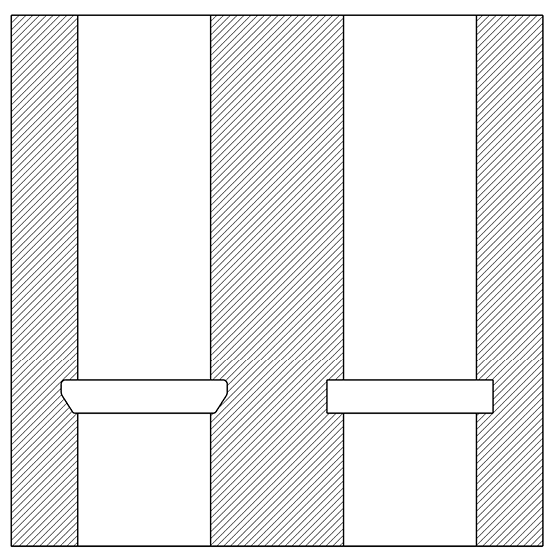
Figure 1. The left bore has a more complex ID groove that requires the use of a custom form tool, whereas the right bore has a straight-sided groove that a standard tool can make.

The power and flexibility of CAD and CAM software and CNC machine tools make machining complex shapes easy and affordable and reduce the need for custom cutters. The first CNC machine tools were developed to make complex aerospace components that could not have been economically produced otherwise.

NC machines use linear and circular interpolation between Cartesian coordinates to produce complex shapes with amazing accuracy. Unfortunately, interpolation does not work when a tool cannot access the area to be machined. Grooves with odd radii, for instance, often require specials. For straight-sided grooves, however, a standard grooving tool can be interpolated to achieve the desired dimensions (Figure 1). Special thread forms (threads are helical grooves) can also require specials.

As noted, a custom sometimes costs less than a standard. For example, I was tasked with reducing tool costs on a NC turning center that used 2.0 "-long, ⅜ "-dia. endmills with a 0.625 " flute length to mill flats on a round part. The milled flats were 0.010 " deep, so only the very end of the tool was used. To save ½ " of carbide per tool and the extra flute grinding expense, I specified a ⅜ " custom endmill that was 1.5 " long and had a 0.250 " flute length.

Many shops perform high-feed milling and high-speed machining and take advantage of chip thinning. These techniques produce toolpaths that have small DOCs and higher-than-normal feed rates. Because the chips produced are small and thin, the milling tool doesn’t require deep flutes. And because feed rates are directly proportional to the number of flutes, more flutes means faster feeds and, therefore, shorter cycle times. Some toolmakers offer cutters specifically for HSM, but the selection is small and the tools are expensive, so a custom may be justified in these situations.

As I’ve urged in past columns, shops should take advantage of NC capabilities to minimize the number of tools stored in a machine’s tool magazine. For example, use circular interpolation with an endmill to enlarge drilled holes rather than using multiple drills, or use an endmill to mill and counterbore instead of loading counterbores.

However, high-production shops often have cycle-time requirements that prevent this approach. Automotive manufacturers machine millions of parts each year and a cycle-time reduction of 1 second leads to significant savings. Therefore, a tool that produces multiple geometric features simultaneously often becomes a necessity. A job shop might create a complex hole using five tools for spot drilling, drilling, reaming, spotfacing and chamfering, whereas a custom combination tool eliminates the need for multiple operations (Figure 2).

FIGURE_2.tif

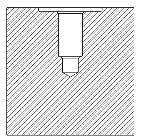
Figure 2. These hole features, which are similar to ports in hydraulic components, could be produced by applying numerous standard tools, but if it’s a high-volume parts application, a custom drill that creates the features in one operation is easy to justify.

Another time, I was tasked with reducing tool costs for a work cell and found that one custom milling tool had marginal performance and added a significant amount of cost to the part. Nonetheless, part geometry required a custom form tool because there was no way to produce the shape with a standard. The original special was a ¾ "-dia., 4-flute endmill with a single cutting end. Because the carbide substrate was about half the tool cost, I saved 35 percent by switching to a double-ended tool with a ⅝ " shank. Also, performance increased by altering the clearance angles on the tool and adding two flutes.

I default to standard tools when planning a new process but do not hesitate to use specials when appropriate. Be creative and ask toolmakers about their ideas for unique solutions. With effective design and planning, custom tools can boost efficiency and profitability. CTE


About the Author: Christopher Tate is senior advanced manufacturing engineering for Milwaukee Electric Tool Corp., Brookfield, Wis. He is based at the company’s manufacturing plant in Jackson, Miss. He has 19 years of experience in the metalworking industry and holds a Master of Science and Bachelor of Science from Mississippi State University. E-mail: chris23state@gmail.com.

Related Glossary Terms

  • chamfering

    chamfering

    Machining a bevel on a workpiece or tool; improves a tool’s entrance into the cut.

  • clearance

    clearance

    Space provided behind a tool’s land or relief to prevent rubbing and subsequent premature deterioration of the tool. See land; relief.

  • computer numerical control ( CNC)

    computer numerical control ( CNC)

    Microprocessor-based controller dedicated to a machine tool that permits the creation or modification of parts. Programmed numerical control activates the machine’s servos and spindle drives and controls the various machining operations. See DNC, direct numerical control; NC, numerical control.

  • computer-aided design ( CAD)

    computer-aided design ( CAD)

    Product-design functions performed with the help of computers and special software.

  • computer-aided manufacturing ( CAM)

    computer-aided manufacturing ( CAM)

    Use of computers to control machining and manufacturing processes.

  • counterbore

    counterbore

    Tool, guided by a pilot, that expands a hole to a certain depth.

  • endmill

    endmill

    Milling cutter held by its shank that cuts on its periphery and, if so configured, on its free end. Takes a variety of shapes (single- and double-end, roughing, ballnose and cup-end) and sizes (stub, medium, long and extra-long). Also comes with differing numbers of flutes.

  • feed

    feed

    Rate of change of position of the tool as a whole, relative to the workpiece while cutting.

  • flutes

    flutes

    Grooves and spaces in the body of a tool that permit chip removal from, and cutting-fluid application to, the point of cut.

  • gang cutting ( milling)

    gang cutting ( milling)

    Machining with several cutters mounted on a single arbor, generally for simultaneous cutting.

  • grinding

    grinding

    Machining operation in which material is removed from the workpiece by a powered abrasive wheel, stone, belt, paste, sheet, compound, slurry, etc. Takes various forms: surface grinding (creates flat and/or squared surfaces); cylindrical grinding (for external cylindrical and tapered shapes, fillets, undercuts, etc.); centerless grinding; chamfering; thread and form grinding; tool and cutter grinding; offhand grinding; lapping and polishing (grinding with extremely fine grits to create ultrasmooth surfaces); honing; and disc grinding.

  • grooving

    grooving

    Machining grooves and shallow channels. Example: grooving ball-bearing raceways. Typically performed by tools that are capable of light cuts at high feed rates. Imparts high-quality finish.

  • inner diameter ( ID)

    inner diameter ( ID)

    Dimension that defines the inside diameter of a cavity or hole. See OD, outer diameter.

  • interpolation

    interpolation

    Process of generating a sufficient number of positioning commands for the servomotors driving the machine tool so the path of the tool closely approximates the ideal path. See CNC, computer numerical control; NC, numerical control.

  • metalworking

    metalworking

    Any manufacturing process in which metal is processed or machined such that the workpiece is given a new shape. Broadly defined, the term includes processes such as design and layout, heat-treating, material handling and inspection.

  • milling

    milling

    Machining operation in which metal or other material is removed by applying power to a rotating cutter. In vertical milling, the cutting tool is mounted vertically on the spindle. In horizontal milling, the cutting tool is mounted horizontally, either directly on the spindle or on an arbor. Horizontal milling is further broken down into conventional milling, where the cutter rotates opposite the direction of feed, or “up” into the workpiece; and climb milling, where the cutter rotates in the direction of feed, or “down” into the workpiece. Milling operations include plane or surface milling, endmilling, facemilling, angle milling, form milling and profiling.

  • milling machine ( mill)

    milling machine ( mill)

    Runs endmills and arbor-mounted milling cutters. Features include a head with a spindle that drives the cutters; a column, knee and table that provide motion in the three Cartesian axes; and a base that supports the components and houses the cutting-fluid pump and reservoir. The work is mounted on the table and fed into the rotating cutter or endmill to accomplish the milling steps; vertical milling machines also feed endmills into the work by means of a spindle-mounted quill. Models range from small manual machines to big bed-type and duplex mills. All take one of three basic forms: vertical, horizontal or convertible horizontal/vertical. Vertical machines may be knee-type (the table is mounted on a knee that can be elevated) or bed-type (the table is securely supported and only moves horizontally). In general, horizontal machines are bigger and more powerful, while vertical machines are lighter but more versatile and easier to set up and operate.

  • numerical control ( NC)

    numerical control ( NC)

    Any controlled equipment that allows an operator to program its movement by entering a series of coded numbers and symbols. See CNC, computer numerical control; DNC, direct numerical control.

  • shank

    shank

    Main body of a tool; the portion of a drill or similar end-held tool that fits into a collet, chuck or similar mounting device.

  • spotfacing

    spotfacing

    Similar to counterboring except that, in spotfacing, material around the original hole is cut. Application example: the recessed area into which a washer fits. See counterboring; countersinking.

  • turning

    turning

    Workpiece is held in a chuck, mounted on a face plate or secured between centers and rotated while a cutting tool, normally a single-point tool, is fed into it along its periphery or across its end or face. Takes the form of straight turning (cutting along the periphery of the workpiece); taper turning (creating a taper); step turning (turning different-size diameters on the same work); chamfering (beveling an edge or shoulder); facing (cutting on an end); turning threads (usually external but can be internal); roughing (high-volume metal removal); and finishing (final light cuts). Performed on lathes, turning centers, chucking machines, automatic screw machines and similar machines.