Producing prototype automotive parts via 3-D printing helps reduce time to market while boosting vehicle quality and fuel efficiency.
More automakers are using 3-D printing, or additive manufacturing (AM), processes to build parts layer by layer, primarily for rapid prototyping.
“While additive manufacturing is fantastic in the prototype space, the cost and the relatively long cycle time prevent it from being a viable option in high-volume manufacturing,” said
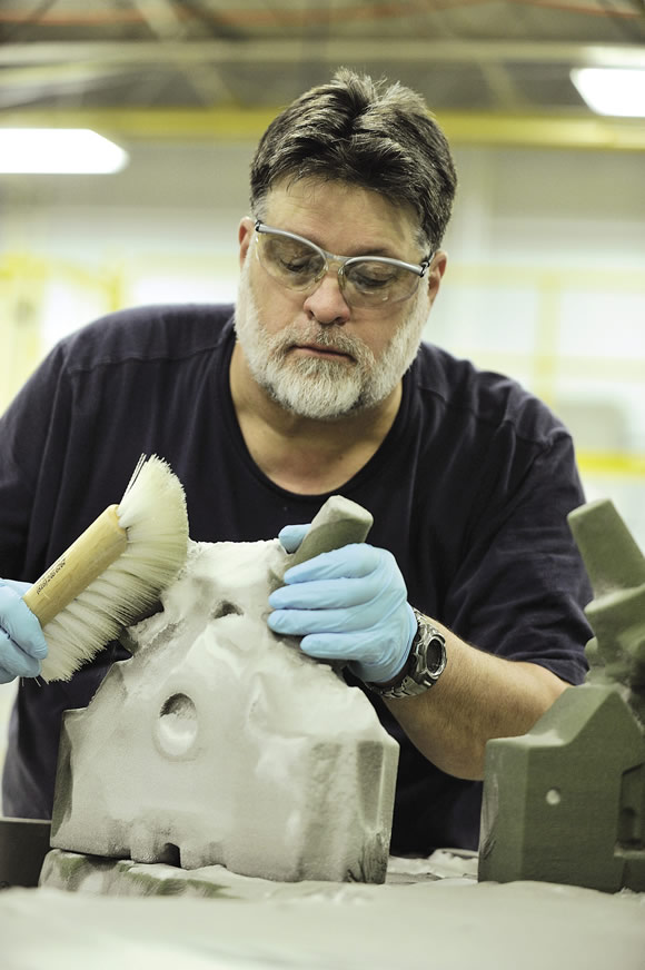
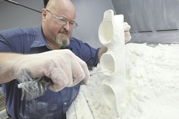
Courtesy of Sam VarnHagen/Ford Motor
Ford Technologist Dennis DuBay removes sand that surrounds a sand cast mold for engine components. The mold was made via Ford’s 3-D printing process at its facility in Dearborn Heights, Mich.
David Bolognino, director of design fabrication for General Motors Co., who is based at the automaker’s Global Design Center in Warren, Mich. He noted an industrial-grade 3-D printer costs about $1 million, and there’s a physical speed limit to scanning a deposited layer of material with a laser. “I don’t see a paradigm shift in the amount of time it takes to build the part from these machines any time soon.”
Others agree, including Muthuraman Ramasamy, senior industry analyst for consultancy Frost & Sullivan, San Antonio, which tracks the 3-D
printing market. “However complex the part is, I don’t think 3-D printing could fit in with mainstream, high-volume, high-speed production processes,” he said. “Unless the 3-D printing process gets refined more and the speed of production increases, it will not be able to match traditional processes like horizontal and vertical machining centers in the near future. It could take a lot of time to reach that state.”
However, specialty, low-volume production parts, as well as tooling, are being produced via AM (see page 53 and 56.)
GM has been rapid prototyping parts since the late 1980s and uses selective laser sintering machines and stereo lithography apparatus (SLA). SLS fuses plastic, ceramic, glass or metal powders in cross sections. A laser then scans a pattern on the surface of the powder, fusing the particles into a layer 0.004 " thick. As each new layer of powder is added, scanned and fused to the previous one, the part takes shape within the 28-cu.-in. reservoir.
If GM cannot produce an entire part within that space, portions are printed and joined with tongue-and-groove joints, pins and glues, Bolognino said. “The technology is only limited by your imagination.” He pointed out that GM doesn’t produce any sintered metal parts, instead choosing to machine a metal billet, use investment casting to produce metal prototypes or outsource machining.
SLA differs from SLS in that it combines photochemistry and laser technology to build parts from liquid photopolymer resins. The parts are built in layers as an ultraviolet laser traces the section onto the photopolymer resin surface, curing the liquid into a solid as it scans. Because the resin won’t often support the parts being formed, a fine, lattice-like structure is generated below each part during the manufacturing process.
A Prevalent Technology
In addition to GM, Ford Motor Co., Toyota Motor Sales U.S.A. Inc. and Daimler AG are some of the other automakers that use the technology.
According to Daimler, it began experimental 3-D printing prototypes in 1990 and currently uses SLA, SLS, selective laser melting, fused deposition modeling (FDM) and thermal fusion technology to create mock-up, plastic designs and functional steel and aluminum parts. Because the processes do not require additional hard tools, such as dies and molds, AM is faster and cheaper than conventional manufacturing.
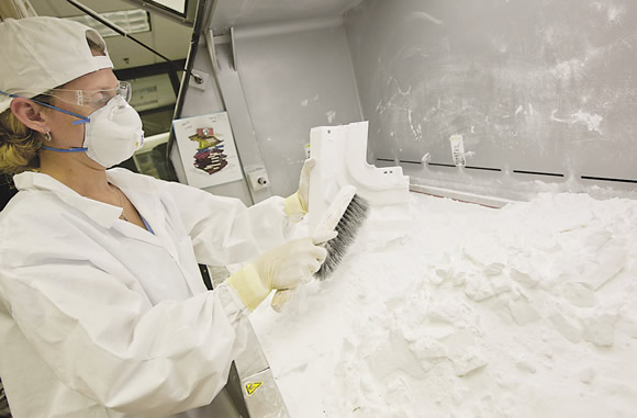
Courtesy of General Motors
GM Global Design’s rapid prototyping laboratory team reclaims and repurposes the powder material used in selective laser sintering, an AM process.
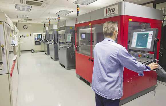
Courtesy of General Motors
The Rapid Prototype Laboratory at the GM Global Design Center operates on a 24/7 schedule for a continuous flow of receiving, scheduling, manufacturing and express shipping of more than 25,000 rapid prototyping components a year using stereo lithography apparatus and selective laser sintering.
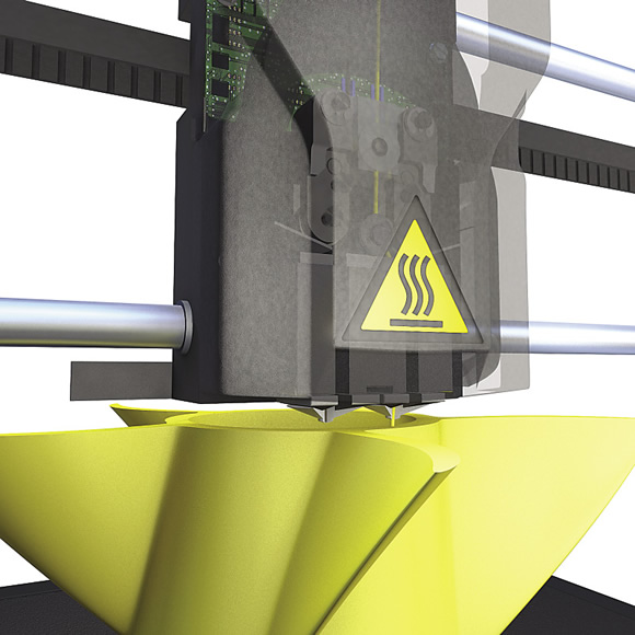
Courtesy of Stratasys
A 3-D printer building a part layer by layer. The printer head is visible below the triangle-shaped logo.
Toyota started rapid prototyping in 1997 and is now prototyping most of the plastic parts on its vehicles, such as instrument panels, inner door panels, wheels and climate controls, mainly for appearance checks, noted Matt Mahaffy, principal engineer, rapid prototyping at Toyota Technical Center U.S.A., Plym-outh, Mich. The AM processes include FDM, SLS and SLA. “The main advantages include the speed at which the parts can be created, the ability to make several variations at the same time and the parts can be created without hard tooling,” he said.
Although Toyota doesn’t typically machine parts after AM, Mahaffy noted they do receive a significant amount of manual work for aesthetic purposes, including sanding, painting and assembly.
Ford’s AM experience dates back to 1988, when it took delivery of an SLA, one of the first commercialized 3-D printing technologies, from 3D Systems, noted Harold P. Sears, additive manufacturing technical specialist at the automaker’s Beech Daly Technical Center, Dearborn, Mich. “Shortly after that, other AM technologies started appearing,” he said, “and Ford invested in many of those technologies as well.”
In addition to large AM machines for industrial applications, such as ones from 3D Systems, EOS, Stratasys and ExOne, Ford employs small, desktop 3-D printers, such as ones from MakerBot, which Stratasys acquired in June. Sears explained that the lower-cost, less-precise desktop machines are for engineers to rapidly develop part designs, like a shift handle, that they can physically hold. They can also transmit files to other engineers, including ones at the company’s design studio in Silicon Valley, who then 3-D print parts for evaluation and discussion. This eliminates the cost and time to ship parts when developing functional prototypes, which then migrate to the more accurate industrial printers.
From Sand to Metal
Ford also has 3-D printing machines to produce sand molds, which it sends to foundries for casting metal parts, such as those made from aluminum, iron, steel and magnesium. Sears explained that the printing process involves feeding silica sand into a machine, where an activator is mixed with the sand. The machine spreads a layer of activated sand over a table and prints a binder on top of the sand, repeating the process until a sand mold is produced similar to a conventional one, possibly including cores and other features, without the hard tooling investment. Ford then finishes the near-net-shape part produced in a mold at the technical center’s machine shop.
“It gives engineers the ability to do multiple iterations and test their components as opposed to the old days where they would design a part, make a tool, make the part, test the part, modify the design and then modify or remake the tool, which is a sequential process,” Sears said. “We moved to a more parallel process, where an engineer can come to us with five or six designs at the same time.”
This enables an engineer to pick the top one or two designs after testing, then refine one to optimize the product. “Without these technologies, we would not be able to meet some of the timing constraints we have today, and, if we did, you probably wouldn’t see the quality that you see today,” Sears said. “In the end, the consumer gets a better product.”
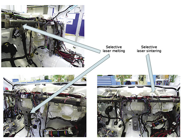
Courtesy of Daimler
Parts in an assembly that Daimler produced using selective laser melting and selective laser sintering.
Nonetheless, Sears emphasized that 3-D printing doesn’t eliminate injection-mold tooling and conventional machining for prototyping. Instead, AM helps engineers prove-out a design before committing to the cost and time for machining conventional tooling and processing.
In another application, the outside dimensions and features of many cast components are often established first, but internal features, such as flow passages, may require additional testing because they are more dynamic, Sears noted. Then, low-cost prototype tooling is used to make the external mold pieces and the internal cores are printed. “Why commit those to a tool until the design is a little more solidified?” he asked.
In addition, sometimes it’s more efficient to machine a metal workpiece, so Ford does. “We don’t try to force the technology just so we can say we do everything with 3-D printing,” Sears said. “Instead, it’s another tool in our toolbox that helps us deliver a better product. Of course, for production, we’re fully tooling everything, because 3-D printing is not nearly fast enough for Ford’s production rates.”
Life of Luxury
Additive manufacturing may never be used for high-volume part production, but it is being used to produce end-use parts for low-volume, high-value vehicles. Just as James Bond wouldn’t be caught dead in an off-the-rack suit, a Bentley Mulsanne customer demands a tailor-made driving experience—even if it’s not from the driver’s seat.
“The markets we’re seeing the most success in are the extremely low-volume, high-cost luxury and performance autos,” said Allen Kreemer, DDM (direct digital manufacturing) automotive technology lead for Stratasys Inc., Eden Prairie, Minn. “It doesn’t make sense to machine an injection-mold tool to make an interior trim panel if you’re producing 20 cars a year.”
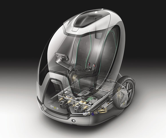
Courtesy of General Motors
The GM Global Design Center’s rapid prototyping capabilities fast-tracked the EN-V (Electric Networked-Vehicle) concept program, which includes this Miao model.
He noted several customers are using Stratasys’ Fortus FDM machines to produce some production parts, as well as using Stratasys’ AM materials and its RedEye business unit, which offers 3-D printing services. One automaker is even seeing more order activity for its custom vehicles than its standard offerings, according to Kreemer.
He explained that the machines only use polymers in filament form, or thermoplastics, to build parts. Those materials include high-strength, high-temperature-resistant and chemical- resistant polymers, such as Ultem 9085 from Sabic. A canister with a spool inside contains a plastic filament, or string, that travels through a machine to the melting head, which melts it into fine strands. The head then travels in the X and Y axes, similar to a cutting tool in a CNC machine, but deposits the part and support material layer by layer in the build area to create a part rather than removing material from a workpiece. The Z table moves downward, away from the head, in user-selected increments called “layers” until the build process is completed. The support material is removed after the build.
Once a part is completed, it can be vibratory polished, blasted with abrasives or otherwise mechanically finished, Kreemer noted. However, surface finish is less critical when the part is covered in leather or some other fabric and a somewhat rough finish often helps when applying spray adhesives for the coverings.
While the extrusion width can vary during the part build process, layer thickness remains constant for the entire build of parts, Kreemer said. “You cannot mix fine layers with coarse layers.”
Rodger Reaume, executive for 3-D printing solutions at Buffalo Grove, Ill.-based Computer Aided Technology Inc., a representative for Stratasys, noted 3-D printers can run unattended to minimize labor requirements.
He added that the FDM machines can deposit up to 3 cu. in. of material per hour, depending on part geometry and how the part is oriented on the build platform. For example, it’s faster to build a horizontally positioned part than one that’s angled vertically.
“Part strength and smoothness, or aesthetics, are other things you have to keep in mind when you’re working within the software to make a great part,” Reaume said, noting that a CAD system’s STL file is read by the software that controls a 3-D printing machine.
However, build speed and part aesthetics often pose roadblocks for manufacturers looking to adopt AM, according to Reaume, even though the process is repeatable and accurate. Users can achieve tolerances of ±0.005 " or better for horizontally built parts.
Although major automakers’ production volumes are too large for AM processes, that’s not the case for their preproduction and concept runs. For instance, Bolognino said the GM Global Design Center’s rapid prototyping capabilities fast-tracked vehicle programs like the Chevrolet Volt hybrid and EN-V (Electric Networked-Vehicle) concept to reduce drag and increase fuel efficiency (see photo on page 53). The EN-V is a two-seat electric vehicle with a balancing system developed by Segway. GM reports that the vehicle is designed to ease traffic congestion, parking availability, air quality and car affordability for tomorrow’s cities, and is produced in three models: Xiao (laugh), Miao (magic) and Jiao (pride).
“Those vehicles were produced in our facility,” Bolognino said, noting about 10 to 15 percent of body and interior parts were created with AM. “They were our largest production fleet ever out of this facility, which totaled 15, or five of each copy. AM is the perfect technology to use for that sort of number.”
Tooling for Industry
In addition to low-volume, high-value parts, some part manufacturers are using AM to create parts that cannot be machined. Reaume pointed out that some printed components have internal moving parts, such as gears, that are held with support material during the build. Afterward, the supports dissolve in a circulation tank containing detergent and water. “These machines are going to print what you put in there, within reason,” he said. “It’s pretty amazing what is possible these days.”
Courtesy of Sam VarnHagen/Ford Motor
Ford Technologist Mark Smith cleans a 3-D printed part at Ford’s 3-D printing facility. The technology allows engineers to quickly create a series of testable pieces with slight variations, a process that helps Ford develop the most fuel-efficient vehicles for mass production.
Major automakers are also using AM to manufacture fixtures, such as for workholding on machine tools and coordinate measuring machines, and assembly tools for workers, such as form-fitting ones that are hollow or have a honeycomb structure to reduce weight. “Then, the worker isn’t carrying around a 5-lb. block of aluminum,” Stratasys’ Kreemer said. “Instead, he has a 1-lb. or less organic-shaped tool that’s wrapped around an ergonomic design. That’s very important in a lot of factories.”
Toyota creates fixtures and templates via rapid prototyping, but for use on internal, prototype vehicle construction and not for mass production, Mahaffy noted.
Other automakers, such as Ford, are developing production applications. “That is probably one of the biggest places we’re seeing more impact from these technologies as they make their way out of just being a design-concept aid to where they’re being used in assembly operations,” Sears said.
Industry Trends
While well-established, 3-D printing still needs improvement, according to some. “For us, the main limitation is that the parts are not produced from the production materials commonly used in our industry,” Toyota’s Mahaffy said.
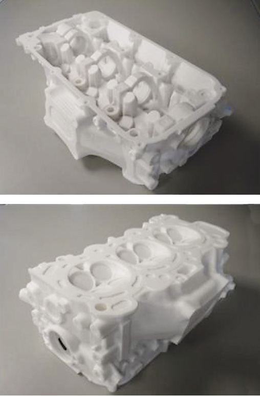
Courtesy of Stratasys
This polycarbonate cylinder head model is for CNC training and was produced on a Stratasys Fortus 400mc machine.
That, however, is rapidly changing. “Clearly, the biggest movement has been in materials,” Bolognino said. GM is one of the first to receive new materials from 3D Systems, he added, and seeks ones that enhance part strength, heat resistance and transparency. “Those are the big three for us.”
Ford’s Sears concurred: “The materials that have become available over the last couple of years are just unbelievable. It seems like almost daily I hear about more materials being developed. Our goal is produce prototypes as close to a production material and production process as possible.”
One new 3-D printing material introduced in late July by ExOne Co., North Huntingdon, Pa., is iron infiltrated with bronze. Iron is widely used in manufacturing auto parts, as well as machine tools and general support structures. “We remain committed to releasing at least one new material every 6 months,” said CEO Rick Lucas, adding that 11 materials are under various stages of development at ExOne’s Material Applications Laboratory.
According to Frost & Sullivan’s Ramasamy, software innovations—which are often downplayed compared to hardware developments—will make designing AM parts seamless, easy and flexible.
“That’s what will be driving the industry moving forward,” he said. “We see a lot of interplay between software and hardware as manufacturing megatrends like Industrial 4.0 (cyber-physical production systems) and Internet of Everything analytics transform the space. It’s a space to watch out for. We could potentially see urban factories co-located within living communities. This future scenario would see 3-D printing complementing existing manufacturing machines.”
Ramasamy envisions that software and connectivity advances will enable collaborative designs by several product designers located across the world. They will be able to upload these designs to an AM Web site, which converts them into the appropriate file format and directs the manufacturing of the parts on a 3-D printer, the packaging of the parts and the shipping of the parts to the next process location. This can be applied on products with longer lead times to avoid hampering production.
“The process of design, manufacturing and logistics can be completely automated until the stage the produced parts arrive at one common location to be assembled,” Ramasamy said. “The idea of removing the human workforce from mundane and repeatable tasks is a juggernaut that is inevitable. This futuristic scenario would potentially automate a major portion of manufacturing process, while yielding impressive productivity, throughput and quality benefits. It could well be the manufacturing value chain of the future.”
At least for the near future, cutting tool makers don’t have to worry about automakers and their suppliers abandoning their products for 3-D printers as AM technologies remain firmly footed in rapid prototyping and low-volume runs, even as developments continue. “The most promising development of all,” Mahaffy said, “is the increasing amount of interest and press the industry and technology are receiving.” CTE
Supersonic car employs 3-D printed titanium prototype
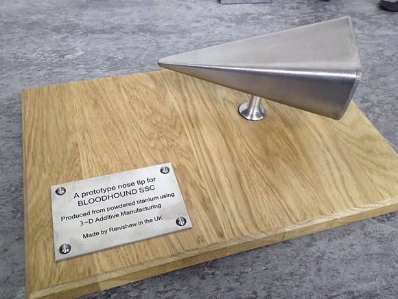
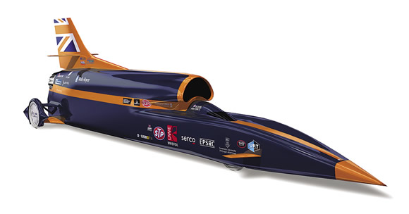
In its ‘HUNT’ to break the 1,000-mph (1,609.3-km/hr.) speed barrier during Summer 2015, the Bloodhound supersonic car project team turned to Renishaw plc, Gloucestershire, U.K., for assistance in 3-D printing a prototype nose tip, a crucial part for the car.
The land speed record is 760.343 mph (1,223.65 km/hr.) and was set Oct. 15, 1997, in the ThrustSSC driven by Andy Green, a British Royal Air Force pilot. He is scheduled to drive the Bloodhound SSC as well.
The nose tip is subject to forces as high as 4,915 lbs./ft.2. To cope with such loads, the team designed and built a Ti6Al4V prototype tip. It will be bonded to the car’s carbon fiber monocoque body, which forms the front half of the car.
The team produced the nose tip with a Renishaw AM250 laser melting machine, which fuses 50µm-thick (0.002 ") layers of fine, gas-atomized metallic powders to form complex parts. The equipment can also build with 25µm layers. The team will use the prototype to evaluate possible manufacturing processes and conduct further engineering analysis.
Courtesy of Renishaw
During his visit to the Bloodhound Technical Center, U.K. Minister for Universities and Science David Willetts received this commemorative plaque with a prototype nose tip, produced via additive manufacturing, for the Bloodhound SSC (inset).
“We believe that the key benefit of using an additive manufacturing process to produce the nose tip is the ability to create a hollow, but highly rigid titanium structure, and to vary the wall thickness of the tip to minimize weight,” said Dan Johns, lead engineer at Bloodhound SSC. He is responsible for materials, processes and technologies. “To machine this component conventionally would be extremely challenging, result in design compromises and waste as much as 95 percent of the expensive raw material as swarf.”
According to Renishaw, wall thickness averages 3mm (0.12 "), with the freedom to create geometric features to aid the bonding process. If the part were to be machined from a solid piece of titanium—which would require milling instead of turning because it does not have a circular cross section—the freedom to create bonding features would be limited. In addition, workholding is challenging because of the part geometry.
In early July, U.K. Minister for Universities and Science David Willetts formally opened the Bloodhound Technical Center in Avonmouth, Bristol, where the supersonic car is being assembled. He also announced a $1.5 million grant from the U.K.’s Engineering and Physical Sciences Research Council to support the Bloodhound project’s education and outreach mission, which aims to inspire children about science, technology, engineering and math subjects.
For more information, visit www.bloodhoundssc.com.
Contributors
Computer Aided Technology Inc.
(888) 308-2284
www.cati.com
Daimler AG
+49 711-17-0
www.daimler.com
ExOne Co.
(877) 773-9663
www.exone.com
Ford Motor Co.
(800) 392-3673
www.ford.com
Frost & Sullivan
(877) GoFROST
www.frost.com
General Motors Co.
(800) 462-8782
www.gm.com
Renishaw plc
+44 1453-52411
www.renishaw.com
Stratasys Inc.
(952) 937-3000
www.stratasys.com
Toyota Motor Sales U.S.A. Inc.
(800) 331-4331
www.toyota.com
Related Glossary Terms
- 3-D
3-D
Way of displaying real-world objects in a natural way by showing depth, height and width. This system uses the X, Y and Z axes.
- centers
centers
Cone-shaped pins that support a workpiece by one or two ends during machining. The centers fit into holes drilled in the workpiece ends. Centers that turn with the workpiece are called “live” centers; those that do not are called “dead” centers.
- computer numerical control ( CNC)
computer numerical control ( CNC)
Microprocessor-based controller dedicated to a machine tool that permits the creation or modification of parts. Programmed numerical control activates the machine’s servos and spindle drives and controls the various machining operations. See DNC, direct numerical control; NC, numerical control.
- computer-aided design ( CAD)
computer-aided design ( CAD)
Product-design functions performed with the help of computers and special software.
- extrusion
extrusion
Conversion of an ingot or billet into lengths of uniform cross section by forcing metal to flow plastically through a die orifice.
- gang cutting ( milling)
gang cutting ( milling)
Machining with several cutters mounted on a single arbor, generally for simultaneous cutting.
- hard tooling
hard tooling
Tooling made for a specific part. Also called dedicated tooling.
- investment casting
investment casting
1. Casting metal into a mold produced by surrounding (investing) an expandable pattern with a refractory slurry that sets at room temperature, after which the wax, plastic or frozen-mercury pattern is removed through the use of heat. Also called precision casting or lost-wax process. 2. Part made by the investment-casting process.
- land
land
Part of the tool body that remains after the flutes are cut.
- lapping compound( powder)
lapping compound( powder)
Light, abrasive material used for finishing a surface.
- milling
milling
Machining operation in which metal or other material is removed by applying power to a rotating cutter. In vertical milling, the cutting tool is mounted vertically on the spindle. In horizontal milling, the cutting tool is mounted horizontally, either directly on the spindle or on an arbor. Horizontal milling is further broken down into conventional milling, where the cutter rotates opposite the direction of feed, or “up” into the workpiece; and climb milling, where the cutter rotates in the direction of feed, or “down” into the workpiece. Milling operations include plane or surface milling, endmilling, facemilling, angle milling, form milling and profiling.
- parallel
parallel
Strip or block of precision-ground stock used to elevate a workpiece, while keeping it parallel to the worktable, to prevent cutter/table contact.
- sintering
sintering
Bonding of adjacent surfaces in a mass of particles by molecular or atomic attraction on heating at high temperatures below the melting temperature of any constituent in the material. Sintering strengthens and increases the density of a powder mass and recrystallizes powder metals.
- swarf
swarf
Metal fines and grinding wheel particles generated during grinding.
- turning
turning
Workpiece is held in a chuck, mounted on a face plate or secured between centers and rotated while a cutting tool, normally a single-point tool, is fed into it along its periphery or across its end or face. Takes the form of straight turning (cutting along the periphery of the workpiece); taper turning (creating a taper); step turning (turning different-size diameters on the same work); chamfering (beveling an edge or shoulder); facing (cutting on an end); turning threads (usually external but can be internal); roughing (high-volume metal removal); and finishing (final light cuts). Performed on lathes, turning centers, chucking machines, automatic screw machines and similar machines.
- web
web
On a rotating tool, the portion of the tool body that joins the lands. Web is thicker at the shank end, relative to the point end, providing maximum torsional strength.
Author

Alan holds a bachelor’s degree in journalism from Southern Illinois University Carbondale. Including his 20 years at CTE, Alan has more than 30 years of trade journalism experience.