Machine-integrated inspection systems can improve quality, profitability
Stopping a machine to measure a workpiece is a waste of time.
Stopping a machine to measure a workpiece is a waste of time. Not only is a high-priced piece of CNC equipment being taken out of production, but the measurements obtained when a machinist leans into a machine with a micrometer or bore gage can’t compare in accuracy to those generated by a coordinate measuring machine or inline probe. Yet shops do just that every day, increasing downtime and jeopardizing part quality. Fortunately, there’s a better way.
Metrology equipment providers have been busier than hummingbirds on a warm spring day, rapidly developing in- situ gaging systems that may eliminate the inspection status quo, common in many shops, of taking it to QC and waiting for someone to check it. Not only do these new systems reduce the cost of inspection and improve machine uptime, they also open the door to unattended machining.
Courtesy of Hexagon Metrology
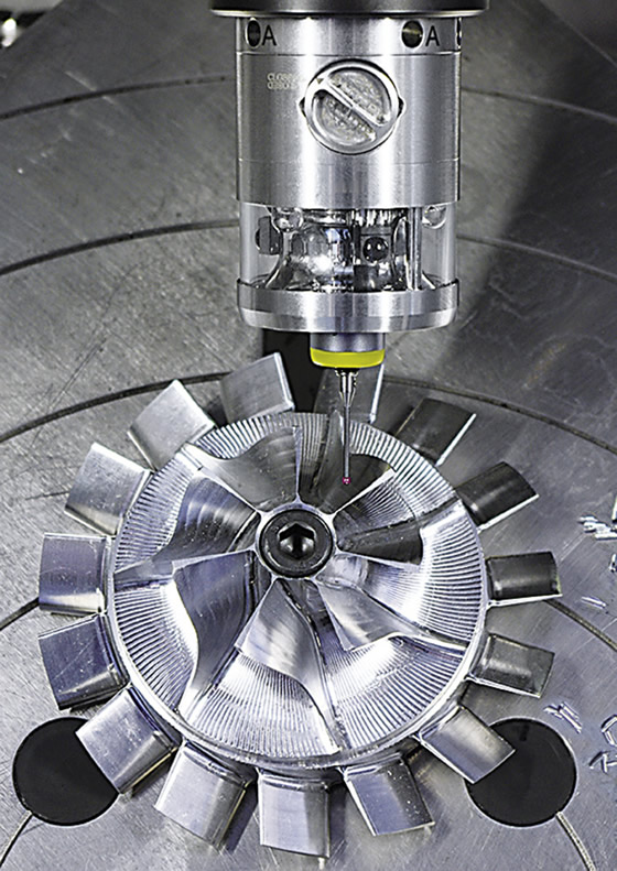
This Hexagon Metrology system supports probe styli as small as 0.2mm (0.008 “) in diameter.
There’s more to this than uptime, however. As part tolerances grow tighter and geometries become increasingly complex, pulling a part out of the machine for measurement makes about as much sense as giving U.S. politicians more paid vacation. When the CMM indicates a bore is undersize by a few tenths, what are the chances of positioning that part in the machine accurately enough to rework it? It’s far better to have this information before the first clamp is ever loosened.
Send CMMs Packing
Machine-mounted probing has been around since the early 1980s. Aimed primarily at setup time reduction and broken tool detection, these devices have evolved into systems as accurate and repeatable as top-caliber machine tools, making it possible to measure a large percentage of part features and all but the tightest part tolerances without ever setting foot in the inspection room.
Intelligence is just as important as accuracy. Adrian Johnson, in-process business manager for Hexagon Metrology Inc., North Kingstown, R.I., said the key development in today’s probing systems is the ability to do in-situ measurement of complex parts.
Courtesy of Hexagon Metrology
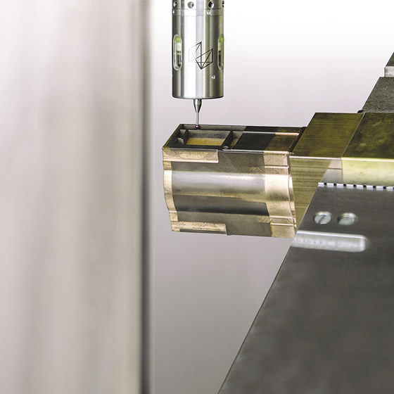
Using a CAD model, the mh40.50 from Hexagon Metrology can inspect macroscale features and those nearly invisible to the naked eye.
Courtesy of Marposs
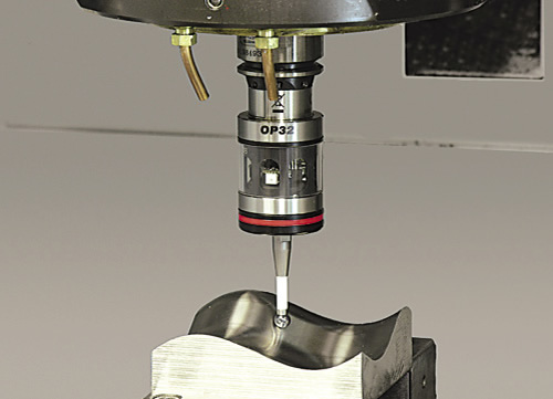
Touch probes, such as Marposs’ OP32 optical transmission probe, help automate machine tools, from setup to on-machine measurement after machining.
“In the past, the primary limitation with machine probes was the CNC software driving them,” he said. “Probes could measure basic things like diameter or length, but they weren’t smart enough to do any sort of detailed dimensional analyses.”
This intelligence allows shops to measure a part, compare it to a CAD model and send real-time corrections to the machine’s CNC. Carried to its logical extreme, a new breed of self-optimizing machine tools may be on the horizon. This isn’t the prelude to some science fiction movie. Johnson said this level of intelligence is available today, giving manufacturers the potential for a cost-effective, closed-loop system able to measure features that would previously have been relegated to the inspection room.
“This is far more than a probe,” Johnson said. “It provides the ability to sense the state of the workpiece and make automatic adjustments to the machining process. Historically, you would try to control this process by inference. If you were machining titanium knee implants, for example, you would try to monitor factors such as tool wear and machine expansion by measuring three or four datum points, then using that information for process control. But if you can understand the real-time geometry of the workpiece by using a probe that’s controlled by smart software, you can catch the end effect of process errors and make adjustments accordingly.”
No Fox in the Henhouse
Some balk at the notion of inspecting parts in the same machine tool on which they were cut. If the machine is out of calibration, there’s little chance of catching potential errors without offline measurement. Sharad Mundra, Mida probing product manager at Marposs Corp., Auburn Hills, Mich., said this concern can be alleviated by using known datum points as part of the machine setup.
“By touching off on these datums—a set of precision tooling balls, for example, located on a nearby component, such as a fixture—the workpiece can be measured relative to these fixed points in space, reducing any concerns about the machine’s volumetric accuracy,” Mundra said. “Machines still require volumetric calibration at regular intervals, but the interval could be reduced by using a datum ball.”
Courtesy of Marposs
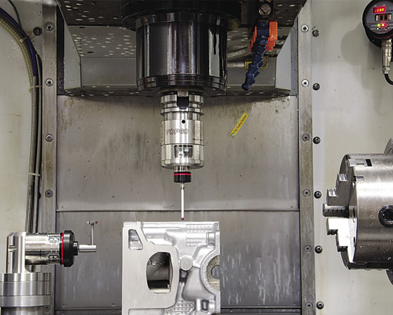
Touch probes, such as Marposs’ Mida VOP, help automate machine tools, from setup to on-machine measurement after machining.
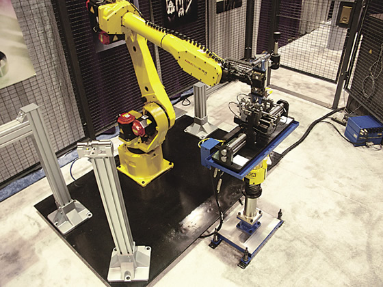
Courtesy of Marposs
A robot loading a machined shaft into a floor-mounted gage. A break-away device protects the gage in case of misalignment.
Mundra conceded that measurements can never be more accurate than the machine tool itself, but with many CNC machines boasting an accuracy of 1µm or better, most part features can be measured in process with a high degree of confidence.
Where probes have historically been used for setting workpiece home positions or measuring tool lengths, Mundra added, they are now capable of much more. Measurement of a part feature results in offset information being sent back to the machine control, or a call is made for a redundant tool once that part feature has deviated from a predefined tolerance band. And if you’re worried about writing the extensive macro programs normally required for complicated decision making such as this, don’t be. Software programs such as CAPPS NC or 3DSI are able to do the heavy lifting and readily integrate with most CAM systems, thus generating the G code needed to drive measurement probes through their paces.
CMMs are likely here to stay, but measuring parts on a machine tool, if done quickly and accurately, makes sense. Avoiding the inspection room saves time and money, and lights-out manufacturing would be all but impossible without some form of automated inspection and feedback to the machine tool. And many workpieces—especially those with tight tolerances and complex geometries—are impossible to put back in the lathe or mill for additional machining once a CMM finds them out of tolerance. Checking parts in the machine with an integrated inspection system effectively validates the machining process, monitors tool wear and gets more parts out the door each day. CTE
Need a sidekick?
Measuring parts in the machine tool isn’t the only path to integrated inspection. Metrology device supplier Renishaw Inc., Hoffman Estates, Ill., offers in-machine probing systems, yet David Chang, technical sales manager of measurement and automation products for Renishaw’s Ontario office, suggested a more conventional approach is often appropriate. The company’s Equator gaging system is, in principle at least, similar to what Marposs’ Sharad Mundra suggested on comparative measurement on CNC machines.
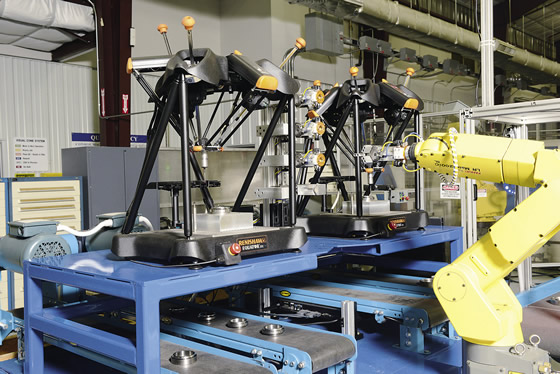
Courtesy of Renishaw
Review the print ads from this magazine to continue
This quick advertiser review unlocks the rest of the article and keeps the full-screen reader focused on the ads instead of the page chrome.


MFGAxis Discussion