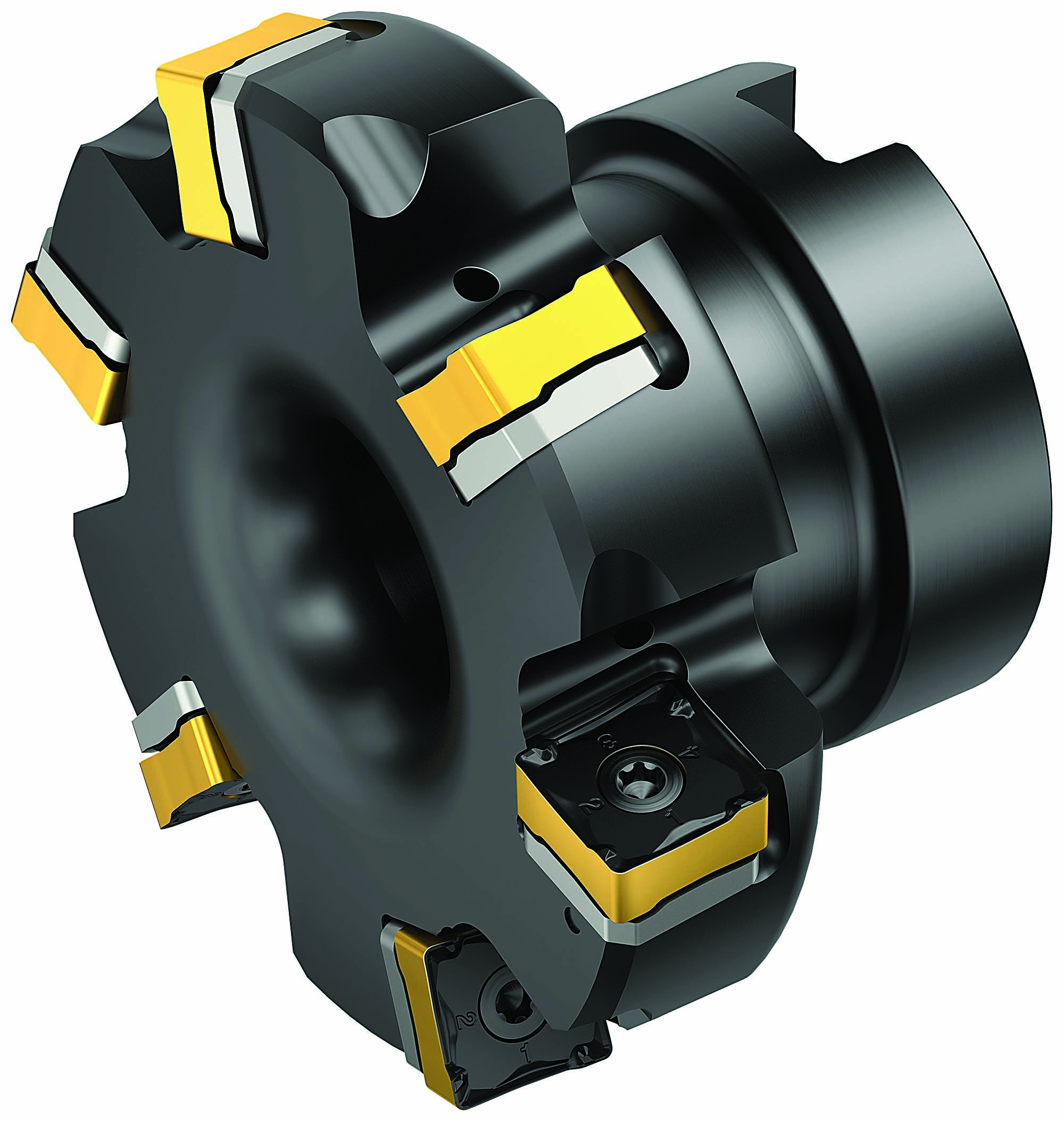
In a recent report, the International Council on Clean Transportation stated that "with the direct correlation of weight and mass, the heavier a vehicle is, the greater its fuel consumption and CO2 emissions. Therefore, reducing mass is an effective way to reduce a vehicle's emissions."One method to achieve this is through lightweighting, which entails building cars and trucks that are less heavy to achieve better fuel efficiency and handling.McKinsey & Co.'s "Lightweight, Heavy Impact" report calculates that "lightweight measures can help reduce CO2 emissions to a certain extent (approximately 0.08 g CO2 reduction per kg saved)." The paper also points out that "if an original equipment manufacturer manages to reduce the vehicle weight by 100 kg, it saves approximately 8.5 g CO2 per 100 km."That example illustrates how lightweighting can benefit vehicle performance. However, although OEMs are embracing lighter materials like aluminum to achieve this, lightweighting is not simply about choosing whichever material weighs the least. Popular materials for automotive parts, such as forged steels, cobalt-chrome, Inconel and grey and nodular cast iron, are still prevalent even though they weigh more than aluminum and magnesium.Instead, manufacturers must engineer these "heavy" metals into being a weight-efficient, strong alternative to lighter metals. That means producing near-net-shape parts based on more complex designs. What's more, many of these designs demand a lighter cutting action to minimize impact on the tool and ensure that the component stays in shape.Shoulder milling is a basic yet versatile milling application recommended for producing a variety of components. Image courtesy of Sandvik Cormorant
The challenge for OEMs is to manufacture these more complex components to the highest quality and with high productivity. But how can manufacturers accomplish this while adhering to emissions regulations and maintaining a low cost per component? The answer lies in more reliable, accurate and productive tooling solutions.
The Right Angle Automotive manufacturers must strive to outperform the competition when machining more complex, near-net-shape parts from tough ISO P materials. Achieving this depends on the choice of cutting tool. For instance, cutting tools with 90-degree lead angles generate radial cutting forces and importantly transfer more cutting energy away from a part. This is ideal when machining parts with thinner walls or near net shapes.
This brings us to shoulder milling, a basic yet versatile milling application recommended for producing a variety of components and when there is a large amount of material to be removed quickly from a workpiece. With shoulder milling, the tool simultaneously creates a plane and shoulder surface, which is why a 90-degree angle to the workpiece is preferred. Other angles can be used depending on the application, but it's essential that the right angle is used to avoid unwanted offsets between the cutter and workpiece.
A number of shoulder milling tooling inserts are on the market designed for a nearly 90-degree milling angle. These inserts generally have eight edges ― four on the front and four on the back to simultaneously produce the shoulder and plane ― or six in some cases. However, Sandvik Coromant Co.'s tooling specialists thought that there was room for a new shoulder milling concept that brings tool life, productivity and economic benefits to customers.
The result is CoroMill MF80, which is designed for automotive milling applications in ISO K and ISO P materials. The inserts have eight cutting edges, chip protection and optimized microgeometry for better security and chip evacuation, as well as a wiper edge for superior surface finish. The cutting edge is inclined for smooth cutting action and low cutting forces, making the insert ideal for thin-walled components and machine setups with limited stability. Based on a technology platform similar to the existing CoroMill 345, this new milling concept offers a 40% lighter cutter body with shim protection and a high number of inserts for secure, stable machining, even in vibration-prone overhang
The 89.5-degree approach angle enables the multi-edge cutter to work close to the fixture while machining. The nearly 90-degree angle also reduces axial forces for improved milling on thin-walled components and weak fixtures without vibration and chatter. This not only improves accuracy and machine utilization but ensures longer tool life with less scrap.
Performance Tests The performance of CoroMill MF80 has been tested against competing mills when machining ISO K and ISO P materials. Let's look first at the ISO K performance test, in which the competing tool and CoroMill MF80 each were used in a roughing application to produce carriers and supports from an ISO K spheroidal graphite iron (GJS400/K3.1.C.UT) workpiece.
CoroMill MF80 is designed for automotive milling applications in ISO K and ISO P materials. Image courtesy of Sandvik Cormorant
Both tools were run with the same cutting data, including a spindle speed (n) of 1,000 rpm, a cutting speed (vc) of 250 m/min. and a table feed (vf) of 1,200 mm/min. Each mill was run with a 20-mm-to-80-mm radial depth of cut (ae) and 2-mm-to-3-mm axial DOC (ap). There was a slight difference in feed per tooth (fz): 0.24 mm for the competing mill and 0.3 mm for CoroMill MF80.
In the end, the competing mill produced 10 components in 55 minutes before showing signs of wear. CoroMill MF80, on the other hand, ran for 82 minutes and
In another example, CoroMill MF80 ran against a competing mill in a rough shoulder milling application to produce pump and valve components from an ISO P carbon steel (DIN 1.0619) workpiece. Again, the mills were run with identical cutting data ― an n of 500 rpm, a vc of 125 m/min., an ae of 15 mm to 50 mm, an ap of 5 mm and an fz of 0.15 mm ― with one exception: the vf. The competing mill ran at 375 mm/min., and CoroMill MF80 ran at 600 mm/min.
In this instance, the competing mill produced nine components while CoroMill MF80 produced 15, a productivity increase of 60%. Also, after 40 minutes of machining, only chipping wear was visible on CoroMill MF80, which increased tool life by 67%. For the customer, the key advantage was that CoroMill MF80's shim protection and the high number of insert edges could lower the cost per part in roughing and shoulder milling applications. Processes like these will be essential in helping manufacturers produce vehicles that meet stringent CO2 emission regulations while maintaining a lower cost per part.
Glossary terms in this article approach angle Angle between the insert’s side-cutting edge and the line perpendicular to the milling cutter’s axis of rotation. Approach angle, which is also known as cutting edge angle, is used…
cutting speed Tangential velocity on the surface of the tool or workpiece at the cutting interface. The formula for cutting speed (sfm) is tool diameter 5 0.26 5 spindle speed (rpm). The formula…
depth of cut Distance between the bottom of the cut and the uncut surface of the workpiece, measured in a direction at right angles to the machined surface of the workpiece.
 Products January 16, 2026 A 5-axis vertical machining center for complex partsAs a solid “first step” into 5-axis machining for some shops, Mazak’s VARIAXIS C-600 offers four spindle options that allow shops to find t…
 Industry News January 14, 2026 Mazak to host Florida Open HouseMazak Corporation has set its sights on the latest manufacturing and automation technology specifically for aerospace, medical, space explo…
 Products January 8, 2026 Machine tracking solution generates real-time machine analyticsThe EZ-SmartTower from Lyndex-Nikken is a machine tracking solution that is designed to increase machine shop efficiency by streamlining RO…
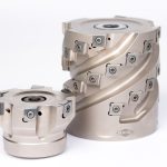 Products January 8, 2026 Milling solutions for semi-finishing and finishingMAPAL expanded its NeoMill milling program with three new series specifically tailored to the requirements of series production: NeoMill-16…