 Figure 1
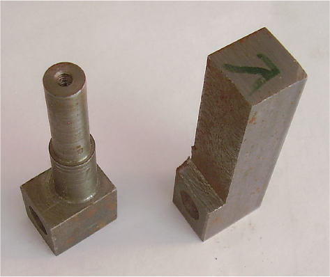 Figure 2
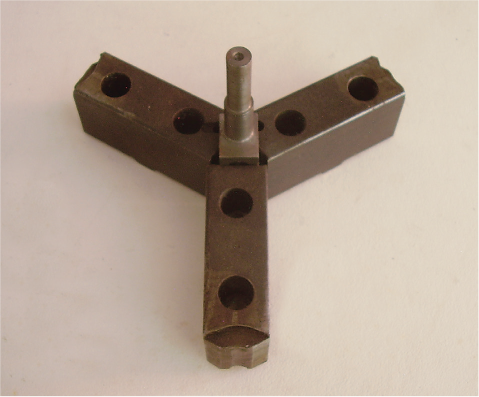 Figure 3
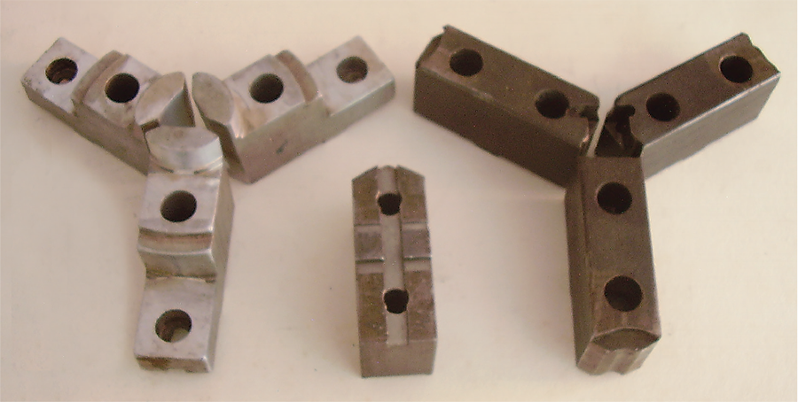
Let’s talk about machining soft jaws for use on a lathe. Figure 1 shows two sets of soft jaws. The jaws on the left are made from 1.25″ × 2.5″ 6061 aluminum flat.
These jaws were made for holding round aluminum parts. The jaws on the right are made from 1.125″ × 1.75″ 1018 steel flat. They were made to hold a rectangular feature on a steel part. Both sets of jaws are made for an 8″ three-jaw scroll chuck with American standard tongue-andgroove mounting. The jaw in the middle shows this mount. The geometry for this mount is in the Machinery Handbook and other places.
I make my own jaws, but sets of jaw blanks ready to be bolted to a chuck are available from tool suppliers. For round parts this is a timesaver. Just bolt the jaws to a chuck, set the diameter of the jaws, and machine the jaws for the part to be held. No milling operations are necessary. When machining the jaws for the part to be held always tighten the chuck in the direction of the clamping force. Use a ring or piece of bar and clamp against it. Details matter.
Figure 2 shows the part for which the steel jaws in Figure 1 were made. It is a spindle for a measuring machine. The finished part is on the left and the blank for the part is on the right. The blank is made on a milling machine from 0.75″ × 1″ 1018 steel flat. A 0.437″ through hole is drilled and reamed and the 1″ dimension is cut to 0.75″ to shorten the lathe operation time. This part could be held on the lathe with a four-jaw independent chuck, but having a set of jaws made for the part on a good scroll chuck makes for better accuracy and repeatability, and saves time per part. Taking care when making the jaws is important.
Figure 3 shows the part in its jaws as it would be on a lathe. To make these jaws, three pieces of 1018 steel were clamped in a milling vice, and the tongue-and-groove mount machined. Then the three-jaw blanks were bolted to an 8″ scroll chuck on an index with the tongue-andgroove mount, and the rectangular feature for holding the spindle was made. See my last article for a picture of the index. The finished jaws then go on the lathe, and the lathe is ready to make money.
For this part, the centerline of the spindle and the 0.437″ through hole must intersect within 0.003″, and this setup hits that mark with ease. I have used this set of jaws to make hundreds of these spindles over the years and I don’t think that my customer ever rejected one. An accurate tool is a good tool. An inaccurate tool is an expensive tool.
Related Glossary Terms
- chuck
chuck
Workholding device that affixes to a mill, lathe or drill-press spindle. It holds a tool or workpiece by one end, allowing it to be rotated. May also be fitted to the machine table to hold a workpiece. Two or more adjustable jaws actually hold the tool or part. May be actuated manually, pneumatically, hydraulically or electrically. See collet.
- flat ( screw flat)
flat ( screw flat)
Flat surface machined into the shank of a cutting tool for enhanced holding of the tool.
- gang cutting ( milling)
gang cutting ( milling)
Machining with several cutters mounted on a single arbor, generally for simultaneous cutting.
- lathe
lathe
Turning machine capable of sawing, milling, grinding, gear-cutting, drilling, reaming, boring, threading, facing, chamfering, grooving, knurling, spinning, parting, necking, taper-cutting, and cam- and eccentric-cutting, as well as step- and straight-turning. Comes in a variety of forms, ranging from manual to semiautomatic to fully automatic, with major types being engine lathes, turning and contouring lathes, turret lathes and numerical-control lathes. The engine lathe consists of a headstock and spindle, tailstock, bed, carriage (complete with apron) and cross slides. Features include gear- (speed) and feed-selector levers, toolpost, compound rest, lead screw and reversing lead screw, threading dial and rapid-traverse lever. Special lathe types include through-the-spindle, camshaft and crankshaft, brake drum and rotor, spinning and gun-barrel machines. Toolroom and bench lathes are used for precision work; the former for tool-and-die work and similar tasks, the latter for small workpieces (instruments, watches), normally without a power feed. Models are typically designated according to their “swing,” or the largest-diameter workpiece that can be rotated; bed length, or the distance between centers; and horsepower generated. See turning machine.
- milling
milling
Machining operation in which metal or other material is removed by applying power to a rotating cutter. In vertical milling, the cutting tool is mounted vertically on the spindle. In horizontal milling, the cutting tool is mounted horizontally, either directly on the spindle or on an arbor. Horizontal milling is further broken down into conventional milling, where the cutter rotates opposite the direction of feed, or “up” into the workpiece; and climb milling, where the cutter rotates in the direction of feed, or “down” into the workpiece. Milling operations include plane or surface milling, endmilling, facemilling, angle milling, form milling and profiling.
- milling machine ( mill)
milling machine ( mill)
Runs endmills and arbor-mounted milling cutters. Features include a head with a spindle that drives the cutters; a column, knee and table that provide motion in the three Cartesian axes; and a base that supports the components and houses the cutting-fluid pump and reservoir. The work is mounted on the table and fed into the rotating cutter or endmill to accomplish the milling steps; vertical milling machines also feed endmills into the work by means of a spindle-mounted quill. Models range from small manual machines to big bed-type and duplex mills. All take one of three basic forms: vertical, horizontal or convertible horizontal/vertical. Vertical machines may be knee-type (the table is mounted on a knee that can be elevated) or bed-type (the table is securely supported and only moves horizontally). In general, horizontal machines are bigger and more powerful, while vertical machines are lighter but more versatile and easier to set up and operate.
Author

Brandt Taylor is owner of Berlin, Massachusetts-based Taylor Engineering, a machine shop.


