More Help for Engineers
More Help for Engineers
In last month's column, I discussed the value of communication between engineers and shop personnel. Here are some additional tips in that vein for engineers:
In last month's column, I discussed the value of communication between engineers and shop personnel. Here are some additional tips in that vein for engineers:
Avoid flippantly adding fillets, radii and chamfers on parts just because it is easy to do with a computer. Such features can substantially increase the time it takes to make parts, as special cutters and additional programming may be needed.


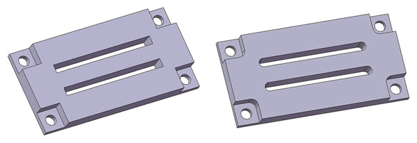
Square corners are nearly impossible to cut with a milling machine. Include radii on pockets and cutouts when possible. All images courtesy J. Harvey.

Avoid showing flat-bottomed holes in drawings unless you actually want the hole to be flat-bottomed. This can be confusing to a machinist, especially if it is not obvious how the hole will be used. Showing a drill tip angle at the
bottom of a hole will remove any doubt as to what you want and make it faster for the machinist to produce. Creating a flat bottom in a hole requires an extra tool or
operation.
Be aware that milled pockets must have a radius somewhere. If you submit a drawing of a part that has pockets or windows with square corners, the job may get sent out for wire EDMing at a substantial cost increase and/or delay to the project.
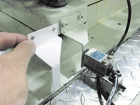
When designing and creating a drawing for a bracket that's added to a machine after it is built, avoid holding a ruler to a machine and saying, "That looks about right." I can almost guarantee you that approach won't work. Instead, go to the machine where the bracket is going to be used and, with a pair of scissors and piece of cardboard, make a model of the bracket. Mark the hole locations on the cardboard—take your time. Then make a drawing of the bracket using the cardboard model as a reference.
I once had to remake a simple bracket a dozen times until it fit on a machine properly. Some machinists see this type of inefficiency as job security. Vendors may love it because they can charge for each revision. I see it as a waste of my time. As one of my respected mentors used to say, "It's easy to make junk."
Be aware that small inside radii take longer to machine than large ones. For machinists, inside radii are more of a concern than outside radii. The larger you can make inside radii in your part designs, the more options you give the machinist in terms of choosing endmill sizes to cut them. The larger the endmill, the faster the part can be made.
Try to maintain consistency in the standard of hardware you use. In other words, stay with either metric or imperial hardware in subsequent add-ons or modifications to a machine or tool.
Try to design parts with parallel surfaces somewhere. Machinists use parallel surfaces to hold parts. If no such surfaces exist, the part becomes difficult to make. If this is not possible, an extension might be added to the part to hold it for machining. After machining the part, the machinist removes the extension and sands the remaining nub flush with the face.
Call out chamfers correctly. I had an issue where I was adding a chamfer to an existing part and the chamfer was called out as 0.17" × 45°. I touched off the 45° cutter to the corner of the part and proceeded to cut in 0.17", as I normally would. I noticed the chamfer was starting to come close to the edge of a tapped hole and hadn't moved the cutter anywhere close to 0.17". That's when I determined the designer had not described correctly what he wanted. The callout actually means the adjacent sides of the "triangle" are 0.17" in length.


Low-tech still has its place. For example, it's a good idea to construct a cardboard model of an odd-shaped bracket to see how it fits on a machine before releasing a drawing.

Pay attention to angle callout for countersunk screw holes. Like it or not, we live in an imperial and metric world. Flathead screws that are tightened down into countersunk holes with angles that don't match will not hold effectively. They will not provide secure and stable fastening. The included angle of a metric countersunk hole is 90°. Imperial countersunk holes are 82°. Attention to this detail is important.
Help shop personnel by ordering special hardware needed for your projects. When a customer brings material and hardware to the shop, I appreciate it. It vastly reduces middlemen and issues with ordering, availability, communication and cost. Furthermore, the shop will likely get started on the project sooner rather than later.


