Pumping innovation
Pumping innovation
April 2009 Part Time column
Eddie Paul opened an auto body shop near Los Angeles in the 1970s. One day a man walked in and asked for delivery of 48 1950s-era cars—within 2 weeks—for an upcoming movie called "Grease." Paul hired local hot-rodders to work on the cars, gathered the appropriate equipment and completed the job on time. Today, E.P. Industries Inc., Segundo, Calif., still builds movie cars, such as 58 vehicles for "The Fast and the Furious" and three rolling, driving, full-size promotional versions of vehicles from the animated movie "Cars." Paul also fabricates and machines products as diverse as artificial sharks for movies and research and a rotating scanner that enables 3-D films to be shot with one camera instead of two.
Less dramatic but no less innovative is E.P. Industries' CEM (Cylindrical Energy Module) positive-displacement rotary pump. Paul invented and patented the pump, which features six double-ended pistons that reciprocate axially in a single cylindrical pump body. CEM pumps are widely used in fire suppression applications, including spraying compressed air foam.
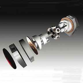
Courtesy of E.P. Industries
Eddie Paul said the wave-shaped split cam of his company's CEM pump is the most difficult of its components to design and machine. In this exploded view of the pump, the mirror-image cam halves are visible next to the bronze-colored mounting plates.
On a pin in the center of each piston is a roller that follows a circular cam around the ID of the pump body. The cam's wave-shaped contour—which looks like a bushing split horizontally into two mirror-image halves—produces the back-and-forth motion of the pistons.
Paul said the CEM pump is smaller and lighter than a positive-displacement piston pump of equal output, or flow volume, and pumps air or liquid in either direction. "I call it a virtual 24-cylinder pump. Six double-ended pistons and two pump cycles per rotation makes 24 pump cycles in one revolution," he said. The pumps typically run at about 1,000 rpm.
Paul makes the pumps in various sizes, ranging from the diameter of a felt-tip marker to 3 ' in diameter.
Despite the size differences, the basic pump design remains the same. "If we need more pumping power we just scale it up," Paul said. "Enlarging the pistons from 1 " to 2 " in diameter, we double the diameters but cube the output; output of 100 gpm with 1 "-dia. pistons grows to 800 gpm with pistons of 2 " in diameter. If we have a 1 "-dia. pump in AutoCAD and somebody wants a ½ "-dia. pump, we take the drawing and scale it by one half and then machine it."
Paul machines pump components from a variety of materials, depending on the application. Most are made from advanced thermoplastic-based resins with ultralow friction characteristics, such as Teflon, Tercite and UHMW-PE. The plastics are basically self-lubricating. "The cam could be Tercite and the rollers might be Teflon," Paul said. "We just need one of the surfaces, usually the cam, to be a lubricant."
Paul said the pump's key component—and the most difficult to design and machine—is the cam that moves the pistons. The two cam halves are identical and interchangeable. For a pump engineered with six 1 "-dia. pistons, each cam half is machined from a piece of ½ "-thick × 4 "-long plastic tubing about 6 " in diameter.
Paul clamps the section of tubing on the table of a Fadal vertical machining center, drills four 1 "-deep axial holes in one end and taps the holes to receive four ¼ "-20 bolts.
To mill the cam profile, Paul attaches the piece of tubing to a plate via bolts in the tapped holes. The plate is then clamped into a 3-jaw chuck on a rotary table mounted perpendicular to the VMC table. An endmill cuts the cam. Movement of the machine's Z and X axes and the rotation of the rotary table combine to produce the wave-like profile. "The cutter has to have the same diameter as the roller that will ride on the cam," Paul said, which is about 1 " in diameter for a typical cam. Depending on the workpiece material, the cutters have three to eight flutes.
Paul said there is no chatter during machining "because we mount it so solidly, and most of the time we are cutting real slow." The rotary table typically turns at 1 rpm while the cutter runs at 600 to 700 rpm. Depending on the cam size and what it's made of, it takes 15 minutes to an hour to machine one cam profile. Cam tolerances are as tight as 0.0005 ", Paul said, noting that other tolerances are not as tight. The cams typically are machined in runs of about 20 pieces.
The cam's shape is critical and application-dependent. When developing the first pump prototypes, "I played with cams for almost 2 years," Paul said. "Now, we have different strokes for different cams. We did one for an oil company where the stroke was three times the length of the bore."
Paul programs the cam-milling toolpaths manually at the Fadal control. "I do it in one paragraph of G code," he said, adding that it generally takes about 5 minutes to program a cam.
Although the basic design of all pump sizes is the same, details vary. The pistons for smaller pumps are made from solid plastic. "However, if we are going to a bigger pump, we may hollow out the pistons because as the length and width double, the weight of the pump is cubed. When you get into something like 4 "-dia. pistons, it is a 500- or 600-lb. pump. In that case, we may make the pistons out of a tube and then cap each end of them."
In addition to a battery-powered fire-suppression unit for residential use, E.P. Industries is also developing an internal combustion-engine version of the CEM pump. Paul said the all-steel, 4-stroke, air-cooled engine will have 12 cylinders and produce at least 2 hp per pound of weight.
Stressing the simplicity of the CEM pump design, Paul said, "When you invent, you design something and then you start taking parts off it until you can't take anything else off. Once it's as simple as possible, then you've got an invention."
For more information about E.P. Industries Inc., visit www.epindustries.com or call (310) 643-8515. CTE