Reducing setup times frees up time for making chips
Reducing setup times frees up time for making chips
Setup reduction is a common goal of every machine shop. Setup does not add value because it does not provide any measureable productivity. In short, when you are not running a machine, you are not making chips, and, therefore, you are not making money. Setup involves numerous non-value-added activities, including tool measurement, fixture alignment and setting coordinate systems, or offsets. As the term suggests, value-adding activities make a workpiece more valuable by changing its shape or physical properties. Many years in and out of machine shops and manufacturing plants have given me ample opportunities to see and establish some unique and familiar methods for reducing setup times and generating savings.
Setup reduction is a common goal of every machine shop. Setup does not add value because it does not provide any measureable productivity. In short, when you are not running a machine, you are not making chips, and, therefore, you are not making money.
Setup involves numerous non-value-added activities, including tool measurement, fixture alignment and setting coordinate systems, or offsets. As the term suggests, value-adding activities make a workpiece more valuable by changing its shape or physical properties.


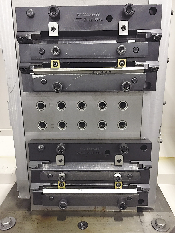
A tombstone on a horizontal toolchanger. See toolchanger/" data-glossary-id="142091" data-glossary-teaser="Mechanism typically included in a machining center that, on the appropriate command, removes one cutting tool from the spindle nose and replaces it with another. The changer restor…" title="Mechanism typically included in a machining center that, on the appropriate command, removes one cutting tool from the spindle nose and replaces it with another. The changer restor…" aria-label="Glossary: automatic toolchanger">automatic toolchanger." title="CNC machine tool capable of drilling, reaming, tapping, milling and boring. Normally comes with an automatic toolchanger. See automatic toolchanger." aria-label="Glossary: machining center">machining center at Mitsubishi Hitachi Power Systems Americas' machine shop is an example of a fixture that can be used on all machining centers, including verticals, because it has a common locating pattern.
All images courtesy C.Tate.

Many years in and out of machine shops and manufacturing plants have given me ample opportunities to see and establish some unique and familiar methods for reducing setup times and generating savings.
For example, I visited a job shop that ran small orders, usually fewer than 25 pieces, and reduced setup times by eliminating tool setting during changeovers. Previously when the shop began a new job, it would remove tools from their holders and replace them with different tools before loading them into the machine. Because the shop generally produced small quantities of parts, a lot of time was consumed taking tools in and out of toolholders.
Then, during a planning phase, the shop identified a set of common tools that could machine the components. Next, it began creating programs that used only the tools on the list. The final step was to purchase a machining center that had a toolchanger with adequate capacity to hold all the tools. After the project was completed, the shop no longer had to set tools during changeovers.
Necessary Function
Tool setting and measuring is a necessity that will never go away. On newer machines, it is possible to automate these processes by embedding electronic data chips into the retention studs of toolholders. These chips record tool measurements from a tool presetter and are read by the machine tool when the toolholder is loaded into the machine. This eliminates error from human input and makes tool setting less disruptive to production.
At a previous job, our shop needed to stock hundreds of special tools for the production of aerospace components. Although our machining center could hold more than 100 tools, it lacked the capacity to hold everything needed for all our jobs. Therefore, we periodically changed tools to support the jobs in our production plan.
Reducing changeover time was a challenge because the age of our machine would not allow the use of embedded-chip technology, but the lead operator in the cell devised a simple plan. After a tool was set and measured, it was labeled with a string tag, which had the necessary tool information on it. Tools were left mounted in their toolholders and stored with their labels so changeover only required the operator to load tools in the appropriate space in the ATC (automatic toolchanger) and enter tool information into the control.
Another Necessity
As with tools, setting and aligning workholders is also a necessity. At Mitsubishi, we use tombstones for horizontal machining centers and plates for vertical machining centers with identical mounting holes evenly spaced in a grid pattern. All fixtures and other workholders have a matching pattern, and dowel pins are employed to align the workholder to the plate or tombstone.
This approach allows us to accurately place the fixture inside the machine and eliminates manual alignment of the workholder to the machine tool. In addition, it can eliminate the need to enter coordinate system values into the control.
When the fixture is accurately returned to the same place inside of the machine's work envelope, it is possible to write a G-code program with the necessary values into the control's memory. This can reduce setup time from hours to minutes.


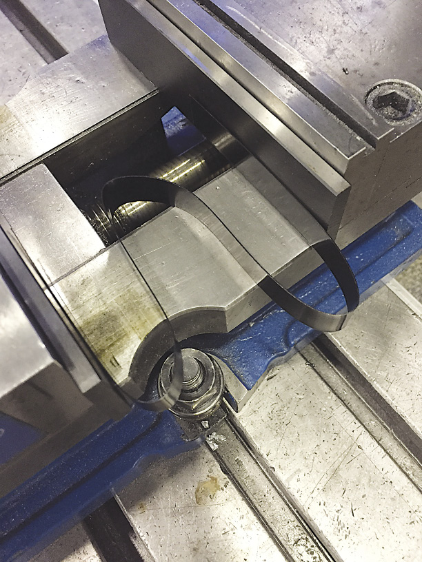
To keep parallels upright when opening a vise, a tool and die maker constructed a spring by bending a piece of banding steel into the pictured shape and placing it between the parallels.

In another example of setup reduction, I found a creative trick at a single-man shop that had no CNC equipment. The owner made special knives for production equipment and finished the various blade angles via surface grinding. Changing angles on the sine plate meant constantly stacking and restacking gage blocks.
He eliminated stacking by making rectangular bars so that each of the three dimensions would set a different blade angle. This entailed simply flipping the bar to the desired side to set the sine plate and then grinding the blade.
I found my favorite time-saver at a small tool and die shop that employed a particularly experienced tool and die maker nicknamed Grandpa. Grandpa was milling several of the same items, so he was constantly taking them in and out of the mill vise. To keep his parallels upright when he opened the vise, he constructed a spring by bending a piece of banding steel into a Z-like shape and placing it between the parallels. While this may not be a true setup-reduction technique, it demonstrates a simple but effective way to save time.
Creativity and imagination are the keys to reducing machine tool setup time. The best solutions usually come from machine operators. One of the best ways to find setup-reduction opportunities is to ask operators what the most-aggravating aspect of setup is. Their answers will almost always lead to time-saving solutions.

Tool Presetters Reduce Setup Time
The benefits of offline presetting for CNC machining are clear. A tool presetter, such as the »venturion« from ZOLLER Inc., Ann Arbor, Mich., reduces setup time for an individual tool by 3 minutes, on average, and because tools are set offline, a presetter can increase production rates.
Tool presetters can be configured to meet the specific needs of various production processes. The measuring equipment is suitable for any CNC production application and for presetting any type of tool, even large, heavy ones. Tools can be set on a presetter located next to a machine tool on the shop floor or in the toolroom.


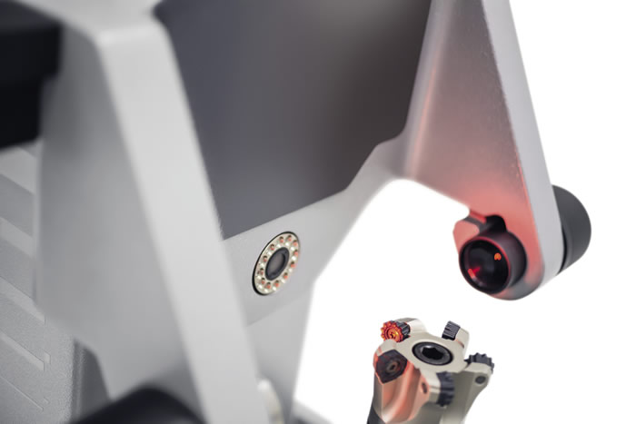
With a tool presetter, cutting tools are set and measured offline while the machine tool is producing parts. Image courtesy Zoller Inc.

In addition, presetting enables CNC— control-oriented data transfers, which make processes more reliable and accurate. This accuracy helps prevents machine crashes and extends tool life.
Presetting also facilitates the inspection of cutting edges for tool wear and inspecting new tools before they are applied in the manufacturing process. This reduces machine downtime and scrap, which increases profits.
A presetter should deliver fast, micron-level measurement results independent of the operator and offer a range of options based on production requirements. Other features that reduce setup time include photorealistic input dialogs, automatic cutting-edge detection and automatic zero-point monitoring.
—ZOLLER Inc.


