Shop Operations: Get your bearings
Shop Operations: Get your bearings
High-quality metrology feedback is one of the cornerstones of precision manufacturing, but that's easier said than done, according to the Shop Operations column in the July 2017 issue of Cutting Tool Engineering magazine.
One of the challenges of running a low-volume job shop is parts inspection. I'm a firm believer that your measuring abilities need to be better than your manufacturing abilities. If you can't measure your output, how can you be sure your output meets specifications?
High-quality metrology feedback is one of the cornerstones of precision manufacturing. This is easy to say and harder to put into practice.
High-quality gages are expensive. If a job is big enough, a shop can amortize gaging costs over a large quantity of parts.
But what if you have one piece to make and the cost of the measuring tool or gage exceeds the total price that you can charge for the part? Situations like this are where job shops must get creative.
Every shop that engages in precision manufacturing should have the fundamental calibrated standards in its metrology arsenal. At the very least, a shop should have a good flat plane, or surface plate, and a set of length standards, or gage blocks. With these standards and a few common measuring tools, a shop can derive and verify almost any measuring challenge.
I also suggest adding a set of precision gage balls to your metrology toolbox.
The production of gage balls is a process of grinding and lapping steel balls to transform them into highly accurate spheres. Common precision balls are accurate to spherical form and to a diametric size of 1µm. For not much additional cost, you can reduce the size and form error by nearly an order of magnitude, putting balls into the realm of the best gage blocks. Most common sizes are available from stock in this accuracy range.
Steel balls allow the clever metrologist to complete a job on time and without having to buy an expensive tool and its calibration standard to measure one part. Afterwards, that new tool may be doomed to sit in a drawer for the rest of its life.
Following are two ways precision balls can be used for measuring jobs.
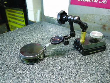
Balls can help when measuring for flatness by firmly supporting a surface plate. Figure 1 shows three balls that are hot-glued to a surface and act as precision kinematic rests that support the part when sweeping the top surface with an indicator to check for flatness.

Figure 1. Three balls are glued down to assist when sweeping the top surface of a plate to check for flatness. All images courtesy of T. Lipton.
The total indicator reading will tell the high-to-low deviation of the indicated surface. The three-point kinematic support assures the plate does not rock during interrogation. Denatured alcohol breaks the hot-glue bond without a fuss.
Precision balls also can act like a ring gage to measure IDs. In addition, only a height gage is needed.

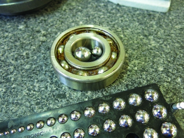
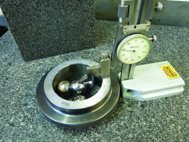
Figure 2. The ID of a ball bearing being measured with two precision balls.
Figure 2 shows two precision balls being used to measure the ID of a ball bearing to an accuracy of 0.0001". The graphical equation for determining the ID can be laid out in any CAD program with the appropriate tangent/tangent relationships, or by using this formula:

The "H" value is the measurement from the surface plate to the top of the highest ball, taken with a height gage. Choosing balls with small vertical distances between their centers makes this a very accurate way to measure ring IDs.

Figure 3: In this four-ball setup, the height is the topmost polar measurement of the center ball from the surface plate, and the three balls in contact with the ID must be the same size.
For larger rings and IDs, it may be more convenient to use four precision balls. Knowing the size of the balls is the only calibration requirement. In Figure 3, H is the topmost polar measurement of the center ball from the surface plate. The formula for the four-ball setup is:

This technique, using readily available precision balls, can replace some expensive three-point internal micrometers and the associated master setting rings.


