Single-piece flow the way to go
Single-piece flow the way to go
Single-piece flow keeps production moving, according to the Shop Technology column in the May 2013 issue of Cutting Tool Engineering.
When we started the Combustion Shop at Savannah Machinery Works' in the fall of 2010, it was vital for us to quickly make changes to machining processes because we were still learning how to make combustion components. We were reacting to tight development schedules and flexibility was critical to producing components quickly and efficiently.
As we enter our third year, the development schedule has slowed and we are settling into a more stable production rhythm. As a result, we are trying to make our processes leaner and to use capital and human resources more efficiently. Demand dictates we build one combustion unit per day. However, we expect demand to steadily increase over the next few years, requiring a corresponding increase in output.

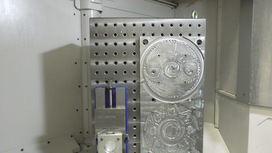
Savannah Machinery Works can produce a fixture, such as this large tombstone with a vise that has a set of machined jaws, in a few hours to solve a machining problem.
We manufacture several different combustor configurations, all in sets of 16.
Combustion assemblies can require hundreds of man-hours to complete, so it is absolutely necessary to have a steady flow of components moving through the manufacturing process.
Combustion components are constructed by machining welded assemblies and subassemblies. In many cases these parts go through a series of welding and machining operations. Welding can take hours, typically several times longer than cycle times for the machining processes, and many assemblies require multiple machining operations.
To maintain a steady flow of product through the processes, we will need to machine components one at a time rather than in complete sets of 16. The lean term for this is "single-piece flow." It requires efficiently switching from one component to the next with minimal setup time, and is essential to meeting production schedules and keeping machining costs in check.

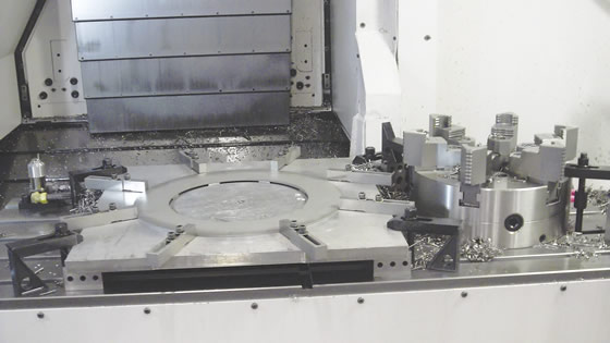
A chuck and a quickly made fixture on a vertical machining center demonstrate Savannah Machinery Works' flexibility.

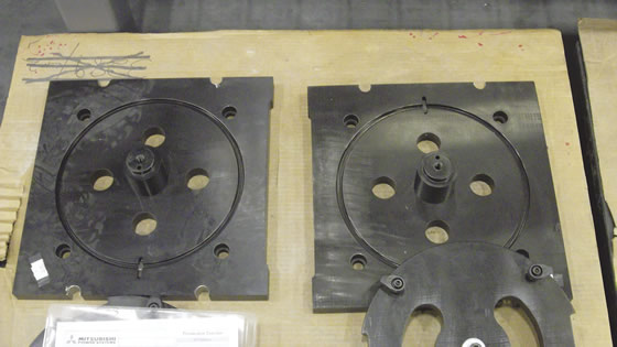
Savannah Machinery Works can set up its new dedicated fixtures to fit on tombstones or subplates and be ready to run in about 10 minutes.
Single-piece flow offers many advantages. By passing the completed component immediately from welding to machining, we eliminate the possibility of a machine tool waiting for the entire batch of components to be completed. Because the subassemblies move through a series of welding and machining processes that build upon each other, starving the machining processes of workpieces also starves the downstream welding processes.
The only way to keep the assemblies flowing through the manufacturing processes would be to have huge amounts of work in process (WIP). But having completed components linger on the floor waiting to move as part of a batch increases inventory, which can quickly burn cash. WIP can also hide defects, whereas producing components one at a time reduces the risk of making multiple ones with the same defect. WIP waiting to be processed is also at risk of being damaged, possibly creating costly rework or scrap. Single-piece flow eliminates WIP.
Our welding processes create inherent variation even when performed by skilled welders. Variation from person to person is usually seen in the amount of shrinkage that occurs in the weld joint. It is often necessary to adjust machining processes to compensate for unexpected weld shrinkage. Adjusting for these occasional occurrences one subassembly at a time allows us to monitor the effects of the adjustment on subsequent processes before having to repeat the step that was altered.
Single-piece flow allows multiple processes to take place simultaneously, ultimately reducing lead times and minimizing the risk of missing shipments. Delivering combustion assemblies on time is vital because most of the units we build are made to support service work. We are contractually obligated to have a turbine back online in a finite amount of time; when the allowable time for service is exceeded, the monetary penalty is enormous.
Single-piece flow will require us to make machine setup simple, with short changeover times. Single-piece flow will also require stable and robust processes to reduce the possibility of producing an unusable product. Stable, robust processes coupled with rapid changeover means less machinist involvement, allowing one person to monitor and load multiple machines.

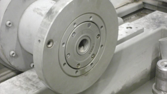
This fixture enables quick changeover on a 6-axis waterjet machine at Savannah Machinery Works.
We plan to start implementing single- piece flow in the second quarter. Implementation will require us to make new programs for the machine tools, new machining fixtures and create methods for identifying cutting tools.
In future columns, I'll chronicle the planning and implementation of single-piece flow along with our successes and failures. CTE
About the Author: Christopher Tate is manufacturing engineering lead for machining at Mitsubishi Power Systems, Savannah (Ga.) Machinery Works, a global builder of gas and steam turbines. He has 19 years of experience in the metalworking industry and holds a Master of Science and Bachelor of Science from Mississippi State University. E-mail: [email protected].
