Turn to form

Author Alan Richter
Published
July 02, 2024 - 01:00pm

It seems counterintuitive that a rotating cutting tool or workpiece can result in the creation of a hexagon, square, Torx, octagon, keyway, serration, involute, spline or other polygon form. “I get people looking at the tool, and they’re like, ‘I don’t care what form you put on the end of this, it’s going to be a circle when it’s done,’” said Steve Derbin, president of Polygon Solutions Inc.

The Fort Myers, Florida, toolmaker offers rotary broaches and rotary broach toolholders and states that the principle that makes this process work is the 1° angle of the cutting tool to the centerline of the workpiece. The angle of the tool causes it to shear the workpiece with a chiseling or scalloping effect as the broach is fed into the part to the depth required. The toolholder has a live spindle that holds the broaching tool, allowing the spindle to spin freely within the toolholder. In a lathe, the spindle is driven by contact with the rotating workpiece. Either way, the tool is only contacting the workpiece at one point during the process, Derbin added, noting that rotary broaching is an extremely fast and accurate way to machine polygon forms, which is why the process is preferred in the medical and aerospace industries.

Polygon Solutions offers a variety of rotary broach toolholers.
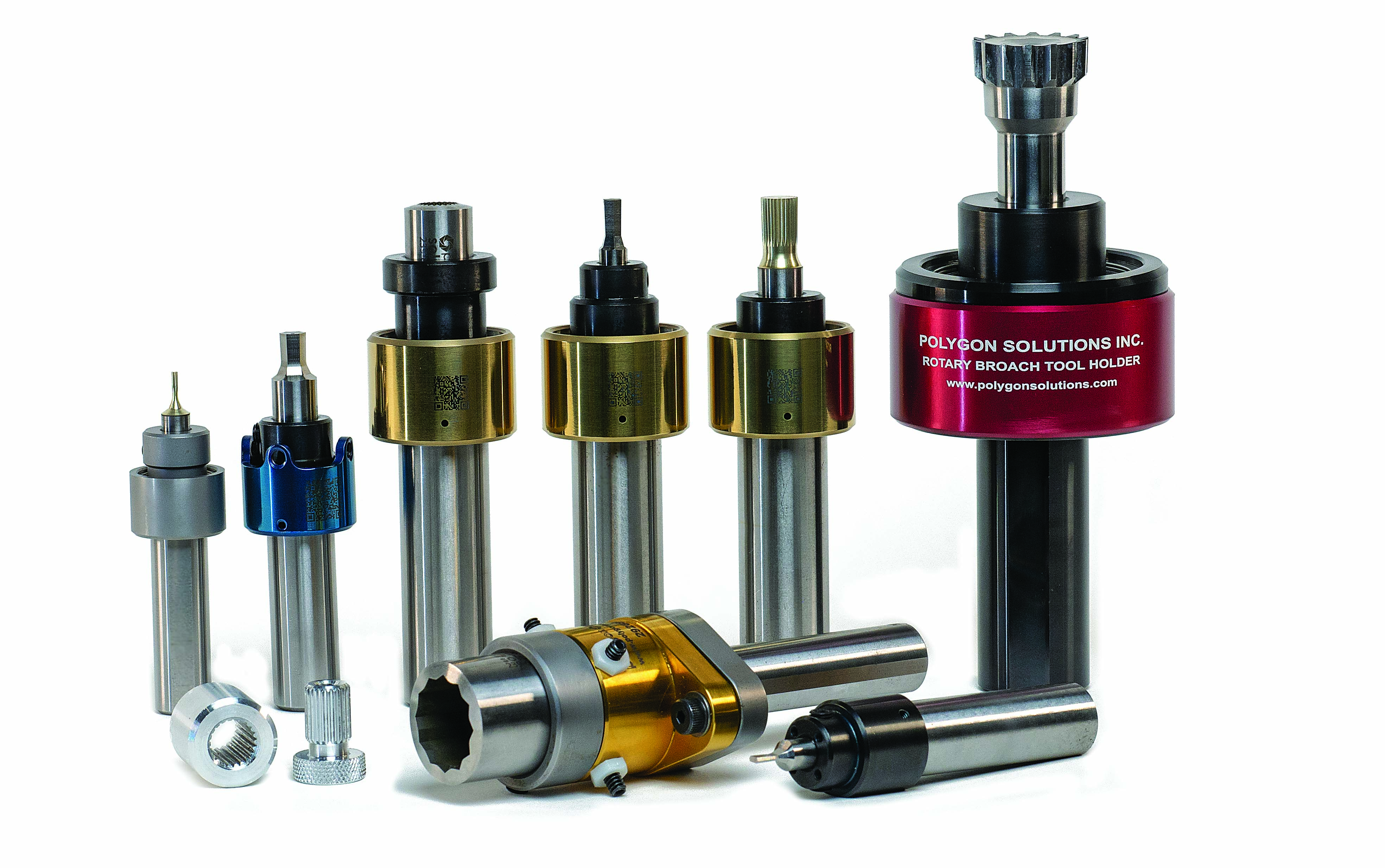
Polygon Solutions offers a variety of rotary broach toolholers. Image courtesy of Polygon Solutions

The broaching method, which can be performed in a matter of seconds to a 0.0127 mm (0.0005") accuracy or better, has been around for a century but that doesn’t mean all metalcutting professionals are familiar with it, he noted. “Every now and then I get a call from a guy who’s been machining 50 years and he’s never seen this before in his life.”

Derbin explained that Polygon’s GT series rotary broach toolholder — its flagship holder — for lathes, mills and turning centers does not need adjustment for fast and simple setup, and has sealed bearings to avoid the need for greasing maintenance, unlike brands that need to be greased every hour or so. “And if your guys on the shop floor are not greasing them, then you’re going to ruin the bearings and start making bad parts quickly.”

Venting Pressure

In addition, the company’s rotary broaches and toolholders come standard with a pressure-relief vent hole system. With a 1 mm (0.039") vent hole through the broaches and out the side of the holders, air and coolant or cutting oil can escape, Derbin said. Not relieving the pressure can have negative consequences. “If you’re doing a blind hole, you can get some kind of vapor lock going on and it puts a lot of pressure on your machine.”

Genevieve Swiss Industries Inc. in Westfield, Massachusetts, also offers tools and holders for rotary broaching through its partnership with Swiss toolmaker PCM Precision Tooling Ltd. GenSwiss offers a pressure-relief vent system as an option when the application is appropriate, said Scott Laprade, applications supervisor. “If you have water-based coolant or oil in the pilot hole that you want to broach and you have a very tight fit between the hex and the pilot hole, you’re going to encounter a situation where it becomes like a hydraulic ram. It’ll just lock up.”

For example, when producing a 6.35 mm (0.250") hexagon socket where the maximum allowable drill diameter is 6.30 mm (0.248") and the broach tool is 6.36 mm (0.2505"), one contiguous chip around the hole perimeter will be pushed in and raise the pressure level significantly, he explained. “In a situation like that you’re going to want to use the vented broach.”

Genevieve Swiss Industries  A diagram of a rotary broaching toolholder with the part and broach centerlines.
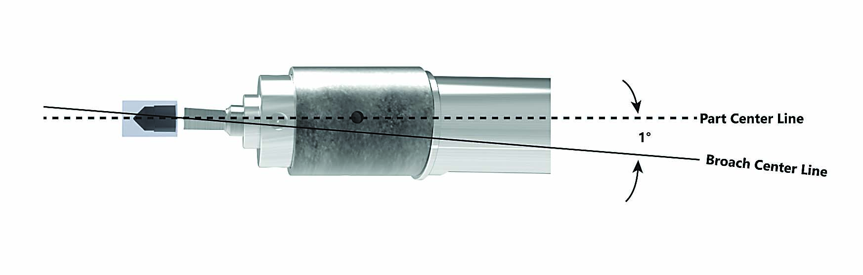
A diagram of a rotary broaching toolholder with the part and broach centerlines. Image courtesy of Genevieve Swiss Industries

Laprade added that, if possible, it might be wise to use a machine that has more Z-axis thrust capability to provide more horsepower on the stroke or shifting to a partial form instead. Partial form broaching enables removing chips and displaced material between indexes, which can be the main reason for rotary broaching being unsuccessful.

He explained the steps for producing a partial form. Spot, drill and chamfer the pilot hole, and then push the partial form into the hole, producing a third of the form per hit and indexing the chuck/spindle between each pass and often clearing the displaced material with a drill between indexes. “You’re making a third of the form at a time and just pushing it in, breaking the material. You push that material in again and do as many passes as it takes in order to get the finished form.”

Machine Matters

As its name implies, GenSwiss focuses on tools and accessories for Swiss-style machining. “GenSwiss was founded to make the Swiss machinist’s life easier,” Laprade said, noting that the company introduced a holder for making it easier to rotary broach on a Swiss-style machine 20 years ago.

Outside the Swiss world, its rotary broaches and holders can be used on turret lathes, milling centers and even manual equipment, he added. “I’ve personally broached on a Bridgeport manually just by cranking either the table or bringing the quill down. You can do it just about on anything where you have either the capability of spinning the workpiece or spinning the holder. Something needs to be rotating.”

While rotary broaching generally eliminates secondary operations where the workpiece is moved from one machine to produce the needed form in another, such as an EDM or punching machine, Laprade noted how rotary broaching in a Swiss machine can eliminate any additional cycle time. By performing the process on the sub-spindle side after the part has already been completed and parted off, it is essentially free time because the front side machines the next part while the sub-spindle broaches.

Genevieve Swiss Industries
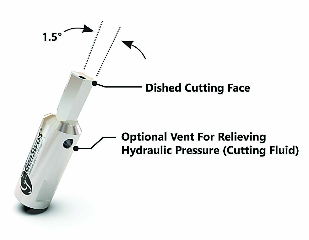
GenSwiss offers rotary broaches with a dished cutting face and optional vent for relieving hydraulic pressure. Image courtesy of Genevieve Swiss Industries

Polygon Solutions reports that its standard broaches are made from M-2 HSS but may also be produced from harder materials such as M-42, powered metal T-15 and PM M-4 HHS. Coatings such as TiN, TiCN and TiAlN can be added for additional strength, longevity and durability. Derbin recommends M-42 for broaching 4140 steel, for example, and PM M-4 for 303 and 304 stainless steel. Polygon also offers a proprietary PS-60 material for broaching exotic materials such as Inconel, titanium and 17-4 stainless steel.

Laprade noted that PCM manufactures its broaches with a specific Swiss formula of tool steel with an 8% cobalt content that is not available from mills in the U.S. “There’s some kind of secret sauce in there that we just can’t quite figure out.”

Tool Guide

A pre-drilled pilot hole is needed for rotary broaching, and the rule of thumb is that the hole is 2% to 3% larger than the cross flats of the form, Derbin said. Because chips curl down the hole being broached, with a hexagon form curling six individual chips, a hole smaller than or the same size of the cross flats would cause one big chip to be pushed down the hole, causing the machine to alarm out or the broach to chip.

“Then you want to put a lead-in chamfer larger than your major diameter, larger than your cross corners,” he said, “and the pre-drilled depth needs to be one and a half times the broaching depth. That way you have room for the chips to accumulate down there. Go back in with your drill and drill out those chips when it’s done.”

To avoid chipping the broach as it enters the hole, Derbin recommends running the spindle at a slow speed, such as 50 rpm, or completely off and touch down into the lead-in chamfer maybe 0.508 mm (0.020") and then going to full spindle speed instead of hitting it head on. Adding a small corner radius, such as 0.127 mm (0.005") can help prevent corners from chipping as well.

A rotary broach brake can be used for multiple-pass broaching.
A rotary broach brake can be used for multiple-pass broaching. Image courtesy of Polygon Solutions

Rotary broaching is not considered a high-speed operation. “You don’t want to risk getting it going too fast and chipping the broach,” Derbin said. “I find that 800 rpm across the range is really good. Now, if you’re in mass production and time is crucial, you could bump it up.”

Laprade noted that rotary broaching provides some “wiggle room” when it comes to machining parameters, altering them to improve the surface finish or extend tool. The highest spindle speed might be 2,000 rpm, but only for small-diameter tools similar to some other machining operations. “Small tools would be a little bit faster rpm, lower feed rate, and bigger tools would be a slower rpm, higher feed rate.”

Proceed With Caution

The more corners the form has that’s being shaped, the easier it is to rotary broach, Laprade said. Compared to a hexagon or octagon, a square has less tangency between the final form and the pilot hole, meaning there is more volume in the corners to be removed.

He added that GenSwiss, which performs rotary broaching in-house to manufacture some of its products, is knowledgeable about which applications are suitable for the process and which ones are not. For example, an application with a cross-hole that’s aligned to a flat on a hex form is difficult to do with a rotary operation because the user does not know where the position of the hex tool in the holder is going to be. “It’s not something that’s controllable. Usually in a situation like that, we advise a punch tool to get a repeatable and stable process.”

According to Laprade, rotary broaching a material as hard as 50 HRC is possible, but tool life suffers and dictates how deep the broach can go and the pilot hole size. “Usually, when someone comes to me and they want to broach hard materials, I give them the rule-of-thumb answer to drill a pilot hole as big as possible and still make a part that’s going to be acceptable. That’s going to give him the best chance of success.”

Genevieve Swiss Indu
Genevieve Swiss Industry
A properly sized pilot hole is critical to successful rotary broaching. Image courtesy of Genevieve Swiss Industries

Derbin concurred that material hardness is one of the main limitations to rotary broaching and tends to shy away from recommending the process for metals harder than 40 HRC. In addition, the form to be broached cannot be too deep. “On larger forms, we can go up to 1¾" deep. That’s about it. On smaller forms like ¼", we can go 1" deep.”

Broach size is another limitation. The Swiss world is known for broaching small forms, but Polygon offers a heavy-duty holder that enables broaching forms up to 50.8 mm (2"), Derbin said. “So, we’re doing some gears for people.”

For manufacturers looking to start rotary broaching and want to produce a range of forms and sizes, he noted that Polygon offers a kit with a toolholder, seven broaches and a carrying case. “The kit is a great option for them because they’re getting a pretty good discount.”

Polygon also offers an alignment brake attachment that allows the broach to be orientated or clocked to the same position for each part, Derbin explained. “If the broached form needs to be clocked to another feature, this is no longer an issue.”

Whether it is used to create a drive socket, fastener, bone screw, mating key, proprietary drive or other feature, the form to be rotary broached must be a symmetrical polygon, Laprade pointed out. “You can’t have any irregularities to it.”

However, when the application is appropriate, rotary broaching can really shine in its ability to machine a polygon quickly, accurately and without a secondary operation. “It’s a really amazing operation,” Derbin said. 


For more information from GenSwiss and Polygon Solutions about rotary broaching, view video presentations at https://qr.ctemag.com/1ta6f and https://qr.ctemag.com/1ta6h


Related Glossary Terms

  • broach

    broach

    Tapered tool, with a series of teeth of increasing length, that is pushed or pulled into a workpiece, successively removing small amounts of metal to enlarge a hole, slot or other opening to final size.

  • broaching

    broaching

    Operation in which a cutter progressively enlarges a slot or hole or shapes a workpiece exterior. Low teeth start the cut, intermediate teeth remove the majority of the material and high teeth finish the task. Broaching can be a one-step operation, as opposed to milling and slotting, which require repeated passes. Typically, however, broaching also involves multiple passes.

  • centers

    centers

    Cone-shaped pins that support a workpiece by one or two ends during machining. The centers fit into holes drilled in the workpiece ends. Centers that turn with the workpiece are called “live” centers; those that do not are called “dead” centers.

  • coolant

    coolant

    Fluid that reduces temperature buildup at the tool/workpiece interface during machining. Normally takes the form of a liquid such as soluble or chemical mixtures (semisynthetic, synthetic) but can be pressurized air or other gas. Because of water’s ability to absorb great quantities of heat, it is widely used as a coolant and vehicle for various cutting compounds, with the water-to-compound ratio varying with the machining task. See cutting fluid; semisynthetic cutting fluid; soluble-oil cutting fluid; synthetic cutting fluid.

  • electrical-discharge machining ( EDM)

    electrical-discharge machining ( EDM)

    Process that vaporizes conductive materials by controlled application of pulsed electrical current that flows between a workpiece and electrode (tool) in a dielectric fluid. Permits machining shapes to tight accuracies without the internal stresses conventional machining often generates. Useful in diemaking.

  • feed

    feed

    Rate of change of position of the tool as a whole, relative to the workpiece while cutting.

  • flat ( screw flat)

    flat ( screw flat)

    Flat surface machined into the shank of a cutting tool for enhanced holding of the tool.

  • gang cutting ( milling)

    gang cutting ( milling)

    Machining with several cutters mounted on a single arbor, generally for simultaneous cutting.

  • hardness

    hardness

    Hardness is a measure of the resistance of a material to surface indentation or abrasion. There is no absolute scale for hardness. In order to express hardness quantitatively, each type of test has its own scale, which defines hardness. Indentation hardness obtained through static methods is measured by Brinell, Rockwell, Vickers and Knoop tests. Hardness without indentation is measured by a dynamic method, known as the Scleroscope test.

  • high-speed steels ( HSS)

    high-speed steels ( HSS)

    Available in two major types: tungsten high-speed steels (designated by letter T having tungsten as the principal alloying element) and molybdenum high-speed steels (designated by letter M having molybdenum as the principal alloying element). The type T high-speed steels containing cobalt have higher wear resistance and greater red (hot) hardness, withstanding cutting temperature up to 1,100º F (590º C). The type T steels are used to fabricate metalcutting tools (milling cutters, drills, reamers and taps), woodworking tools, various types of punches and dies, ball and roller bearings. The type M steels are used for cutting tools and various types of dies.

  • lathe

    lathe

    Turning machine capable of sawing, milling, grinding, gear-cutting, drilling, reaming, boring, threading, facing, chamfering, grooving, knurling, spinning, parting, necking, taper-cutting, and cam- and eccentric-cutting, as well as step- and straight-turning. Comes in a variety of forms, ranging from manual to semiautomatic to fully automatic, with major types being engine lathes, turning and contouring lathes, turret lathes and numerical-control lathes. The engine lathe consists of a headstock and spindle, tailstock, bed, carriage (complete with apron) and cross slides. Features include gear- (speed) and feed-selector levers, toolpost, compound rest, lead screw and reversing lead screw, threading dial and rapid-traverse lever. Special lathe types include through-the-spindle, camshaft and crankshaft, brake drum and rotor, spinning and gun-barrel machines. Toolroom and bench lathes are used for precision work; the former for tool-and-die work and similar tasks, the latter for small workpieces (instruments, watches), normally without a power feed. Models are typically designated according to their “swing,” or the largest-diameter workpiece that can be rotated; bed length, or the distance between centers; and horsepower generated. See turning machine.

  • metalcutting ( material cutting)

    metalcutting ( material cutting)

    Any machining process used to part metal or other material or give a workpiece a new configuration. Conventionally applies to machining operations in which a cutting tool mechanically removes material in the form of chips; applies to any process in which metal or material is removed to create new shapes. See metalforming.

  • milling

    milling

    Machining operation in which metal or other material is removed by applying power to a rotating cutter. In vertical milling, the cutting tool is mounted vertically on the spindle. In horizontal milling, the cutting tool is mounted horizontally, either directly on the spindle or on an arbor. Horizontal milling is further broken down into conventional milling, where the cutter rotates opposite the direction of feed, or “up” into the workpiece; and climb milling, where the cutter rotates in the direction of feed, or “down” into the workpiece. Milling operations include plane or surface milling, endmilling, facemilling, angle milling, form milling and profiling.

  • scalloping

    scalloping

    Wavy surface condition caused by deflection, unbalanced tool, loose workpiece or tooling or worn machine.

  • titanium aluminum nitride ( TiAlN)

    titanium aluminum nitride ( TiAlN)

    Often used as a tool coating. AlTiN indicates the aluminum content is greater than the titanium. See coated tools.

  • titanium carbonitride ( TiCN)

    titanium carbonitride ( TiCN)

    Often used as a tool coating. See coated tools.

  • titanium nitride ( TiN)

    titanium nitride ( TiN)

    Added to titanium-carbide tooling to permit machining of hard metals at high speeds. Also used as a tool coating. See coated tools.

  • toolholder

    toolholder

    Secures a cutting tool during a machining operation. Basic types include block, cartridge, chuck, collet, fixed, modular, quick-change and rotating.

  • turning

    turning

    Workpiece is held in a chuck, mounted on a face plate or secured between centers and rotated while a cutting tool, normally a single-point tool, is fed into it along its periphery or across its end or face. Takes the form of straight turning (cutting along the periphery of the workpiece); taper turning (creating a taper); step turning (turning different-size diameters on the same work); chamfering (beveling an edge or shoulder); facing (cutting on an end); turning threads (usually external but can be internal); roughing (high-volume metal removal); and finishing (final light cuts). Performed on lathes, turning centers, chucking machines, automatic screw machines and similar machines.

Author

Editor-at-large

Alan holds a bachelor’s degree in journalism from Southern Illinois University Carbondale. Including his 20 years at CTE, Alan has more than 30 years of trade journalism experience.

Contributors

Genevieve Swiss Industries Inc.
413-562-4800
www.genswiss.com

Polygon Solutions Inc.
239-628-4800
www.polygonsolutions.com