Understanding Cutting Equations for Feeds and Speeds
Cutting equations connect speed, feed, diameter, and force so shops can estimate spindle demand and process behavior before they cut metal.
Quick take: Cutting equations matter because they connect feeds, speeds, diameter, force, and spindle demand in one decision framework. This page is most useful when it is paired with tangential-force and calculator references during actual setup planning.
Related references: Understanding Tangential Cutting Force in Milling, Calculated Forces When Turning: Quick Guide, and Formula Resources.
If you are balancing cycle time and quality, verify feed target first, then confirm spindle speed and chip-load compatibility before setting final parameters.
Surface feet per minute, chip load, undeformed chip thickness and chip thinning are familiar shop terms. Over the last few weeks, however, several occurrences in our shop have made me realize there are a lot of metalworking professionals who don’t understand these terms and the calculations that go along with them. Whether you work at a small job shop or a large contract manufacturer, it is important to understand cutting tool calculations and how to use them to help drive significant efficiency gains.
Cutting speed calculations might well be the most important ones. They are easy to use and, with a little explanation, easy to understand. The cutting speed of a tool is expressed in surface feet per minute (sfm) or surface meters per minute (m/min.). Similar to mph for a car, sfm is the linear distance a cutting tool travels per minute. To get a better sense of scale, 300 sfm, for example, converts to 3.4 mph.
Toolmakers recommend cutting speeds for different types of workpiece materials. When a toolmaker suggests 100 sfm, it is indicating the outside surface of the rotating tool should travel at a rate of speed equal to 100 linear feet per minute. If the tool has a circumference (diameter × π) of 12″, it would need to rotate at 100 rpm to achieve 100 sfm.
All images courtesy C. Tate
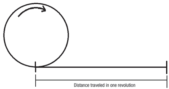
Imagine the cutting tool as a rolling ring or cylinder. The distance traveled in one revolution times rpm is its surface speed. If the circle above had a diameter of 3.82″, the circumference would be 12″. As a result, every revolution would produce a linear distance of 1′, and a spindle speed of 100 rpm would be a cutting speed of 100 sfm.
The following equation is used to calculate spindle speed: rpm = sfm ÷ diameter × 3.82, where diameter is the cutting tool diameter or the part diameter on a lathe in inches, and 3.82 is a constant that comes from an algebraic simplifica-tion of the more complex formula: rpm = (sfm × 12) ÷ (diameter × π).
Review the print ads from this magazine to continue
This quick advertiser review unlocks the rest of the article and keeps the full-screen reader focused on the ads instead of the page chrome.
Advertisers included in this article experience
Print placements connected to this article
Iscarmetals
MAX AR
) B Ultimate Insert Clamping Guarantees Supreme Tool Life Jet Pressure with Free Unobstructed Unique Chipbreakers Chip Flow for Ultimate for Ultimate Insert Life Blade Life Parting and Parting and Parting and Parting and Parting and Parting and Parting and Grooving Grooving for Grooving for Grooving for Grooving for Grooving for Grooving for for Cr-Ni Alloys.
) MAX AR B Ultimate Insert Clamping Guarantees Supreme Tool Life Jet Pressure with Free Unobstructed Unique Chipbreakers Chip Flow for Ultimate for Ultimate Insert Life Blade Life Parting and Parting and Parting and Parting and Parting and Parting and Parting and Grooving Grooving for Grooving for Grooving for Grooving for Grooving for Grooving for for Cr-Ni Alloys, Hard Materials Hard Materials Hard Materials Soft Materials Soft Materials Stainless Steel Ductile Materials and
Visit Iscarmetals View this placement in the issue recordPrint ads from this magazine
) B Ultimate Insert Clamping Guarantees Supreme Tool Life Jet Pressure with Free Unobstructed Unique Chipbreakers Chip Flow for Ultimate for Ultimate Insert Life Blade Life Parting and Parting and Parting and Parting and Parting and Parting and Parting and Grooving Grooving for Grooving for Grooving for Grooving for Grooving for Grooving for for Cr-Ni Alloys.
) MAX AR B Ultimate Insert Clamping Guarantees Supreme Tool Life Jet Pressure with Free Unobstructed Unique Chipbreakers Chip Flow for Ultimate for Ultimate Insert Life Blade Life Parting and Parting and Parting and Parting and Parting and Parting and Parting and Grooving Grooving for Grooving for Grooving for Grooving for Grooving for Grooving for for Cr-Ni Alloys, Hard Materials Hard Materials Hard Materials Soft Materials Soft Materials Stainless Steel Ductile Materials and
Continue reading
July 2014
You can play around with this formula in this Online Calculator
Because the tool diameter is measured in inches, the “feet” in sfm must be converted to inches, and because there are 12 inches in a foot, multiply sfm by 12. In addition, the circumference of the tool is found by multiplying the tool diameter by π, or 3.14 to simplify. The result is: rpm = (sfm × 12) ÷ (diameter × π) = (sfm ÷ diameter) × (12 ÷ π) = (sfm ÷ diameter) × 3.82.
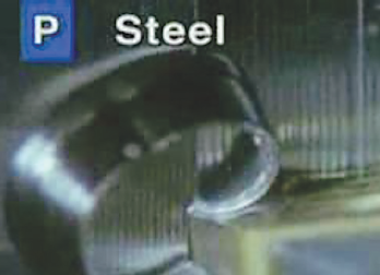
Notice the vertical lines, called tool marks, on the outside of the part being turned. As the feed rate increases, the distance between the lines also increases. The chip thickness is roughly equal to the feed.
Cutting speeds are published in sfm because the ideal cutting speed for a particular family of tools will, in theory, be the same no matter the size of the tool. The engineer, programmer or machinist is expected to calculate the rpm needed to produce the proper cutting speed for each selected tool.
So what is this telling us? Let’s say a 1″-dia. tool must run at 100 sfm. Based on the equation, that tool must turn at 382 rpm to achieve 100 sfm: 100 ÷ 1 × 3.82 = 382.
Another way to consider this concept is to think about the distance the 1″ tool would travel were it to make 382 revolutions across the shop floor. In that scenario, it would travel 100′; do it in 60 seconds and it would be traveling 100 sfm.
Lathes are different, of course, because the workpiece rotates instead of the cutter. Because the formula for cutting speed is dependent on diameter, as the diameter of the workpiece decreases, rpm must increase to maintain a constant surface speed. After each circular cut on the lathe, the workpiece OD decreases or the ID increases, and it is necessary for the rpm of the part to increase to maintain the desired cutting speed. As a result, CNC manufacturers developed the constant surface footage feature for lathe controls. This feature allows the programmer to input the desired cutting speed in sfm or m/min. and the control calculates the proper rpm for the changing diameter.
While the tool or part is spinning, the machine must know how fast to travel while the cutter is engaged in the workpiece. Feed rate is the term that describes the traverse rate while cutting.
Feed rate for milling is usually expressed in inches per minute (ipm) and calculated using: ipm = rpm × no. of flutes × chip load.
Feed-rate planning note: Start with RPM, flute count, and chip load, then verify the result against rigidity, radial engagement, and the actual finish target. For a cleaner worksheet, pair this article with Formula Resources and the Comprehensive Threading Calculators.
Formula: Feed Rate = RPM × Number of Flutes × Chip Load.
Related Reading
- For more on formula, see this related guide.
- Related guide: Cutting Force Resources.
- Related guide: Go Resources.
- Related guide: Calculate.
Glossary terms in this article
Related


Subscribers can use MFGAxis notes, saves and discussion tools with their InnoNet account.