Understanding Tangential Cutting Force in Milling
Tangential cutting force helps shops estimate torque, spindle load, and stability in milling.
Quick take: Tangential force matters because it links milling engagement to torque, spindle load, and process stability. This page is most useful when it is read together with cutting equations, lead-angle, and force-estimation references.
Related references: Understanding Cutting Equations for Feeds and Speeds, Getting to Know the Lead Angle, and Cutting Force Resources.
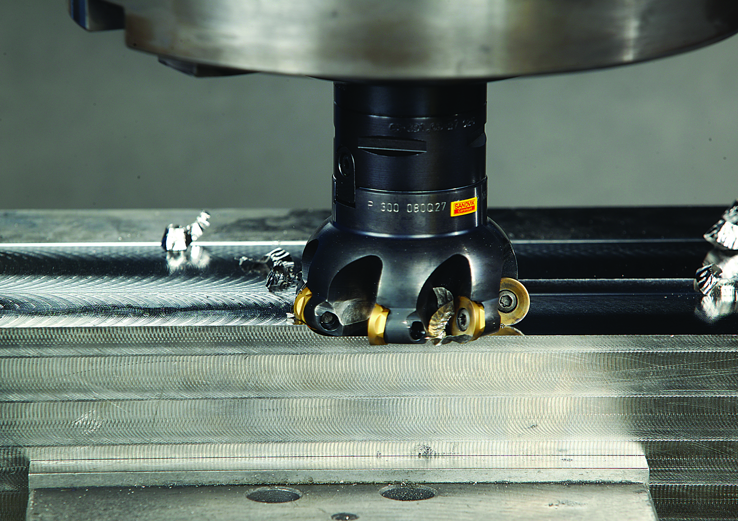
Image courtesy of Sandvik Coromat
[Editor’s Note: This article was written in response to request by Matt Cawyer at Four State Industrial Supply Co. Inc., Carthage, Mo., who wrote the author seeking a formula to determine the torque required by a cutting tool when milling the titanium alloy Ti6Al4V.]
The tangential cutting force, if end users know how to determine it, and the cutting speed, which is selected as one of several machining parameters, allow calculating the required machining power for an operation. When the required machining power value is about the same as the milling machine’s rated power, milling productivity approaches its maximum.
Torque (Ts) that is applied to the spindle, and therefore to the milling cutter, is generated by the tangential cutting force (Ft) and can be calculated by the formula:
Ts = Ft × R (1)
Where R is a radius of a milling cutter. (Formulas are referenced later by the number in parentheses.)
Torque (Ts) Calculator
Torque (Ts):
function calculateTorque() { const Ft = parseFloat(document.getElementById(‘Ft’).value); const radius = parseFloat(document.getElementById(‘radius’).value); if (!isNaN(Ft) && !isNaN(radius)) { const Ts = Ft * radius; document.getElementById(‘resultTorque’).textContent = `Torque (Ts): ${Ts.toFixed(2)} in-lbs`; } else { document.getElementById(‘resultTorque’).textContent = “Please enter valid inputs.”; }}
Formula: Ts = Ft × R
The concept of calculating tangential cutting force when milling is based on the author’s analytical study of metalcutting principles and experimental study of milling cutters with positive-negative and double-positive geometries.
This concept is based on relationships between the following parameters:
- Ultimate tensile strength (σ) of metallic work materials vs. their hardness,
- Cross-sectional area of the uncut chip (A),
- Number of teeth engaged with a workpiece (Zc),
- Engagement factor of a workpiece material (Ef), and
- Cutting tool wear factor (Tf).
The following tangential cutting force formula was developed in accordance with these relationships:
Ft = σ × A × Zc × Ef × Tf (2)
Tangential Cutting Force (Ft) Calculator
Tangential Cutting Force (Ft):
function calculateFt() { const sigma = parseFloat(document.getElementById(‘sigma’).value); const area = parseFloat(document.getElementById(‘area’).value); const teethEngaged = parseFloat(document.getElementById(‘teethEngaged’).value); const engagementFactor = parseFloat(document.getElementById(‘engagementFactor’).value); const wearFactor = parseFloat(document.getElementById(‘wearFactor’).value); if (!isNaN(sigma) && !isNaN(area) && !isNaN(teethEngaged) && !isNaN(engagementFactor) && !isNaN(wearFactor)) { const Ft = sigma * area * teethEngaged * engagementFactor * wearFactor; document.getElementById(‘resultFt’).textContent = `Tangential Cutting Force (Ft): ${Ft.toFixed(2)} lbs`; } else { document.getElementById(‘resultFt’).textContent = “Please enter valid inputs.”; }}
Formula: Ft = σ × A × Zc × Ef × Tf
Because of the end user’s interest in milling a specific titanium alloy, the following information is provided about Ti6Al4V, an alpha-beta titanium alloy. It is used for making aircraft gas turbine discs and blades, airframe structural components and other applications requiring high strength at temperatures up to 600° F (315° C).
The ultimate tensile strength of Ti6Al4V at its annealed condition is 137,000 psi (945 MPa in the metric system), having a hardness of 36 HRC.
The shape of the uncut chip’s cross section depends on the cutting insert geometry and the milling cutter’s lead angle. Square, hexagonal or octagonal inserts have straight cutting edges and produce chips with a rectangular cross section when the milling cutter has a 0° lead angle or a parallelogram cross section when the milling cutter has a lead angle greater than 0°.
The following formula is recommended for calculating the cross-sectional area of the uncut chip:
A = ap × f (3)
Where ap is the axial DOC and f is the feed per tooth, or chip load.
The number of teeth engaged with a workpiece (Zc) depends on the number of teeth in the cutter (Z) and the engagement angle (α). The formula for calculating Zc is:
Zc = Z × α ÷ 360° (4)
The engagement angle depends on the radial WOC (W). If the radial WOC equals the milling cutter diameter (D), the engagement angle has a maximum value of 180°, and the number of engaged teeth is half the number of teeth in the cutter:
Zc = Z × 180° ÷ 360º = 0.5 Z (5)
If the engagement angle is less than 180°, it is calculated by formulas containing trigonometric functions. Detailed description of these formulas and supporting illustrations were published in the July 2010 issue of CTE (see “New Mill” by E. Isakov, p. 44).
Engagement Factors
The engagement factor of a workpiece material (Ef) is a dimensionless coefficient included in formula (2) to correlate tangential cutting force with the ratio of the radial WOC to the cutter diameter (W ÷ D).
Milling is more effective when sufficiently thick and uniform chips are produced. The W/D ratio affects uniformity of the chip thickness. When the radial WOC equals the cutter diameter (W ÷ D = 1), the chip being formed starts at zero thickness at the point of entry. It then increases to a maximum thickness at the centerline of the cutter and thins to zero at the point of exit. This type of cut produces a nonuniform chip, generates maximum friction at the cutting edge and, as a result, increases the chip’s resistance to being cut. Effective milling is obtained when the radial WOC is about two-thirds of the cutter diameter. Such a cut produces uniform and sufficiently thick chips, generates less friction at the cutting edge and decreases cutting resistance.
Cutting Tool Wear Factors
The cutting tool wear factor (Tf) is a dimensionless coefficient included in formula (2) to correlate tangential cutting force with increasing wear of the cutting inserts when milling. When applying new or just indexed cutting inserts for a short time (20 to 25 percent of tool life), the cutting tool wear factor (Tf) is 1.0; when milling until the inserts must be indexed or replaced (100 percent of tool life), the following cutting tool wear factors are recommended according to the type of operation (Machinery’s Handbook, 29th Edition, p. 1,086).
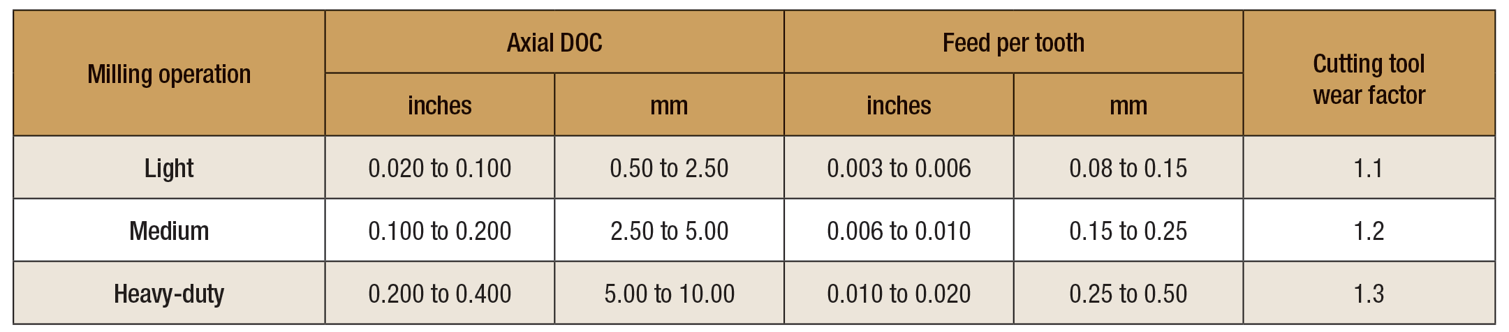
Table. Responses from metalworking professionals describing milling operations by optimal ranges of axial DOC and feed per tooth.
- Light and medium facemilling: 1.10 to 1.25
- Extra-heavy-duty facemilling: 1.30 to 1.60
Unfortunately, the publications reviewed by the author do not have data that could identify each milling operation. Therefore, the author prepared a questionnaire requesting machining data that would best describe the milling operations by optimal ranges of axial DOC and feed per tooth. The questionnaire was sent to more than 100 industrial professionals with practical knowledge and experience in milling applications and more than 80 percent responded. Statistical treatment of their responses produced the data shown in the table above.
Machining Power
Having calculated tangential cutting (Ft), the machining power requirement at the spindle (Ps) and main drive (Pm) can be calculated by the following formulas.
Customary U.S. units of measurement:
Power at spindle: Ps = Ft × Vc ÷ 33,000 (hp) (6)
Power at main drive: Pm = Ps ÷ E (hp) (7)
Where Ft is expressed in pounds, Vc is the cutting speed in sfm, 33,000 is a factor converting ft.-lbs. per minute into horsepower, and E is a main drive efficiency factor expressed as a percentage.
Metric units of measurement:
Power at spindle: Ps = Ft × Vc ÷ 60,000 (kW) (8)
Power at main drive: Pm = Ps ÷ E (kW) (9)
Where Ft is in newtons, Vc is the cutting speed expressed in m/min., 60,000 is a factor converting newton × m/min. into kilowatts, and E is a main drive efficiency factor expressed as a percentage.
Power at Spindle (Ps) Calculator
Power at Spindle (Ps):
function calculatePowerSpindle() { const Ft = parseFloat(document.getElementById(‘FtSpindle’).value); const Vc = parseFloat(document.getElementById(‘Vc’).value); if (!isNaN(Ft) && !isNaN(Vc)) { const Ps = (Ft * Vc) / 33000; document.getElementById(‘resultPowerSpindle’).textContent = `Power at Spindle (Ps): ${Ps.toFixed(2)} hp`; } else { document.getElementById(‘resultPowerSpindle’).textContent = “Please enter valid inputs.”; }}
Formula: Ps = Ft × Vc ÷ 33,000 (in hp)
Main Drive Power (Pm) Calculator
Power at Main Drive (Pm):
function calculatePowerMainDrive() { const Ps = parseFloat(document.getElementById(‘Ps’).value); const efficiency = parseFloat(document.getElementById(‘efficiency’).value) / 100; if (!isNaN(Ps) && !isNaN(efficiency)) { const Pm = Ps / efficiency; document.getElementById(‘resultPowerMainDrive’).textContent = `Power at Main Drive (Pm): ${Pm.toFixed(2)} hp`; } else { document.getElementById(‘resultPowerMainDrive’).textContent = “Please enter valid inputs.”; }}
Formula: Pm = Ps ÷ E
Review the print ads from this magazine to continue
This quick advertiser review unlocks the rest of the article and keeps the full-screen reader focused on the ads instead of the page chrome.


MFGAxis Discussion