Complex machining tasks made easy
Complex machining tasks made easy
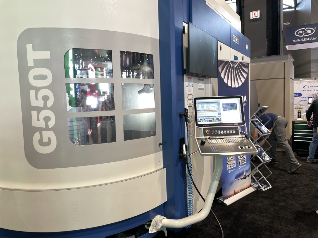
One method to solve manufacturing needs is to utilize fast, close tolerance, and flexible machine tools such as the GROB G550T 5-Axis Mill/ Turn Universal milling and boring. Normally comes with an automatic toolchanger. See automatic toolchanger." title="CNC machine tool capable of drilling, reaming, tapping, milling and boring. Normally comes with an automatic toolchanger. See automatic toolchanger." aria-label="Glossary: machining center">Machining Center and the G150 5-Axis Universal Machining Center.

Automation and digitalization are critical to modern manufacturing. Manufacturers are looking to improve efficiency, reduce costs and enhance part quality. Also, finding and retaining skilled labor is an ongoing challenge for most manufacturers, job shops, and other metal working companies.
How do you solve these problems and make quality and efficiency improvements? One solution, says Doug Lieurance, application engineer for GROB Systems in Bluffton, Ohio, is to utilize fast, close tolerance, and flexible machine tools such as the GROB G550T 5-Axis Mill/ Turn Universal milling and boring. Normally comes with an automatic toolchanger. See automatic toolchanger." title="CNC machine tool capable of drilling, reaming, tapping, milling and boring. Normally comes with an automatic toolchanger. See automatic toolchanger." aria-label="Glossary: machining center">Machining Center that, he explained, is built for highly demanding manufacturing environs.
GROB machining centers, which are compatible with Industry 4.0 principles, are made in the U.S.A. at the GROB Systems full production facility in Ohio and often include advanced automation solutions for dramatically increased productivity. Having the machining center and automation come from the same builder offers customers streamlined service and support to keep the entire cell running at long-term high efficiency. GROB machines feature a unique machine concept including a horizontal spindle position that permits the longest possible Z-travel path and optimum chip fall.
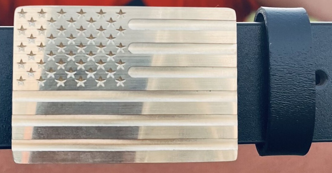
At the recent International Manufacturing Technology Show (IMTS) in Chicago, Lieurance showed Cutting Tool Engineering magazine how the G550T machine handles complex parts. Machining demonstrations were held throughout the day, and not only did visitors to the booth learn about complex machining with 5-axis equipment, some were awarded a belt buckle machined live at the show.
 A belt buckle machined at the show with GROB equipment with programming by Six Digma.">
The G550T, he said, dramatically reduces downtime compared to previous 5-axis machines. It can be operated unattended, which saves on man-hours for manufacturing; and features unparalleled accuracy and consistency that has reduced the need for frequent accuracy measurements.
It can machine a part by milling and turning in a single setup, saving time, costs and floor space. The machine was equipped with a Siemens 840D SL control, 14,500 rpm spindle, and an HSK-T100 tool interface. For maximum stability and machining performance, the G550T featured a powerful mill-turn table with t-slots arranged in a star shape. Three linear and two rotary axes permitted 5-sided machining, as well as 5-axis simultaneous interpolation, with a swivel range of 230 degrees in the A-axis and 360 degrees in the B-axis. The drive design is based on two symmetrically located ball screws, weight compensation in the Y-axis, and wear-free torque motors in the A and B axes.
"Here, we are machining upside down so all the chips from the workpiece that we are cutting are falling right into the chip conveyor, so we have no build up on the pallet or anything like that," he said in describing the machining operation at the show. "Tool change happens completely outside of the work area, so we don't have to worry about the interference with the workpiece, the max size tool, max workpiece, zero collision, anything like that."
At the show, GROB was utilizing sophisticated programming from the Six Digma software development company, Lieurance said. "We connect CAD/CAM and CNC to solve the toughest manufacturing problems," said Edwin Gasparraj, Founder and Principal Consultant, SixDigma.
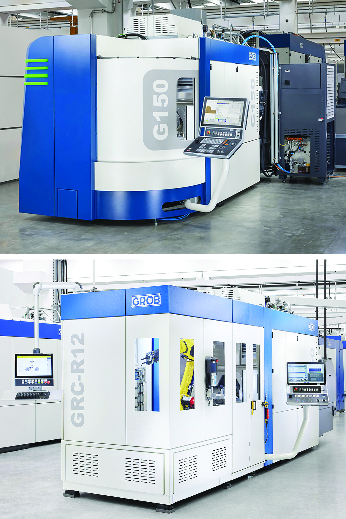
The demonstration at the Allied booth wasn't the only prominent booth at which GROB was displaying its products. At the YG-1 Tool Co. booth GROB showcased its G150 5-Axis Universal Machining Center integrated with the GRC-R12 Robot Cell, which were both under power. Multiple machining demonstrations were held throughout each day.
 The GROB 150 machining center paired with a GRC-R12 robotic center">
The G150 provides high precision, complex machining in a compact size with a smaller work envelope and features direct and absolute position encoders in all axes. Paired with the compact GRC-R12 Robot Cell, productivity was increased even further by offering a flexible, customizable, and affordable automation solution. The cell utilized a 6-Axis FANUC M-10iD/12 Robot with 4.7' (1,441 mm) reach, capable of handling a maximum load of 26.5 lbs (12 kg). The GRC-R12 featured a pneumatic single-or double-gripper system. The drawer feed system can hold up to six drawers that can be unloaded and reloaded while the robot cell and machining center are in operation.
Attendees also got to see demonstrations including an aerospace hydraulic manifold milled from 4140 steel supported by hyperMILL CAM programming from OPEN MIND Technologies.


