Optimal cleanliness leads to the next optimal step
Optimal cleanliness leads to the next optimal step
Parts cleaning is critical to achieving precision, process reliability and high efficiency in processes and production technologies.
Parts cleaning is critical to achieving precision, process reliability and high efficiency in processes and production technologies.
This involves achieving the necessary level of cleanliness for the next production step, such as coating or measuring, reliably yet at reduced operating costs.
At the same time, the trend towards automating and digitizing processes is playing an ever-more important role. Consequently, even where it concerns smaller components, manufacturers prefer a dry and fully automated cleaning solution such as the quattroClean snow-jet technology from acp systems AG.
Remove dried impurities
This was also the case with a valve manufacturer. The valve in question is a rotationally symmetrical part made of steel with a diameter of approximately five millimeters and a length of around five millimeters, which is partially coated in a PVD process.
After machining, which generates heat, the surface is soiled with a mixture of dried-on machining medium (oil) and particles that is difficult to clean off. Although the amount of dirt is comparatively small, it is essential that it is removed from certain areas in order to ensure optimum adhesion and a long-lasting coating. A wet-chemical cleaning process was ruled out because of the high effort, space requirements and energy consumption associated with drying.
Optimally preparing surfaces
Extensive cleaning tests in the acp systems technical center demonstrated that partial cleaning with the quattroClean snow jet technology achieves the cleanliness needed to obtain an optimal coating result. The process uses liquid carbon dioxide as a medium. CO2 is a by-product of chemical manufacturing processes and biogas energy generation, thus making it climate neutral.
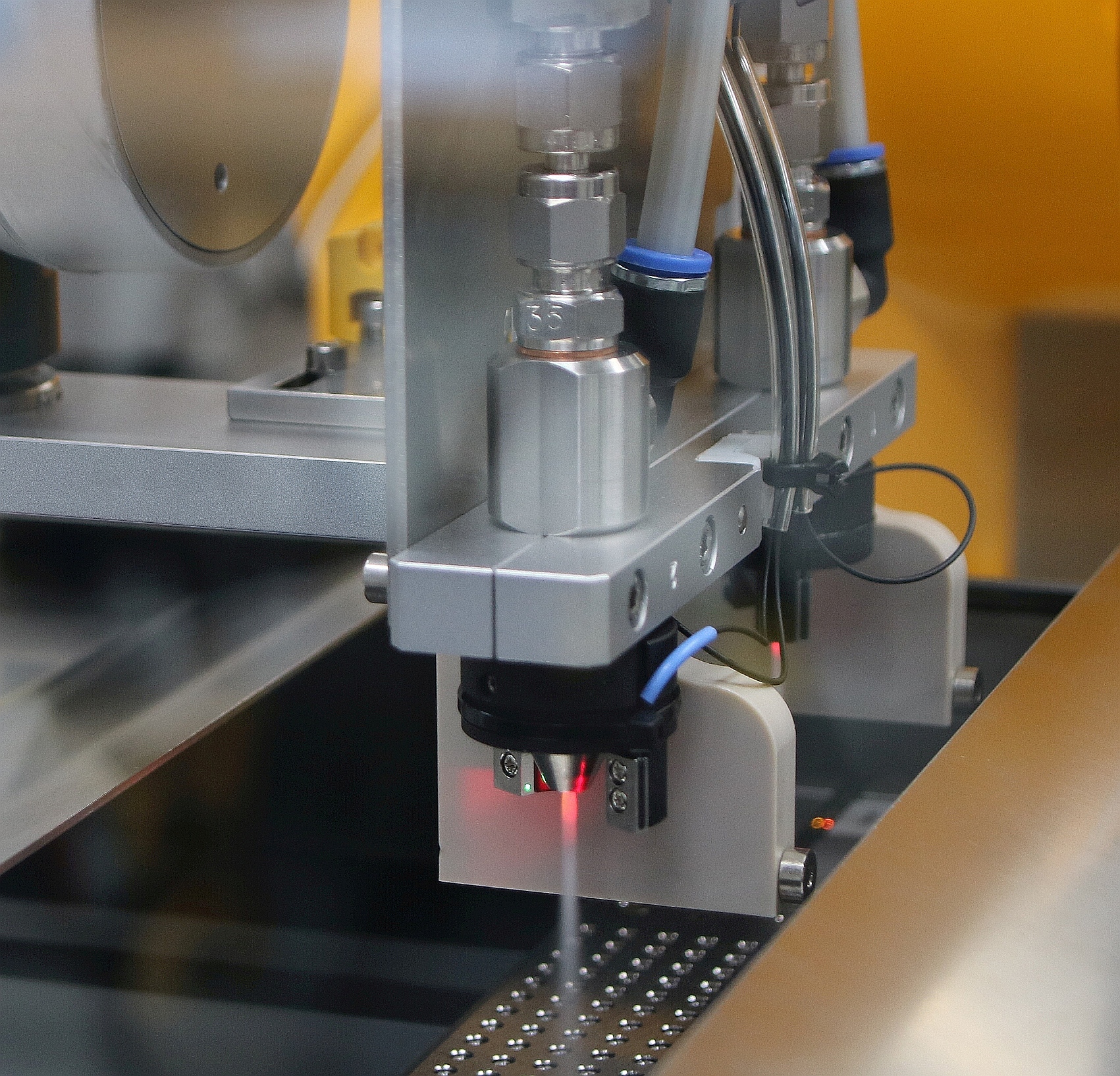
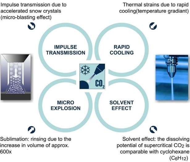
In the cleaning process, liquid carbon dioxide is passed through the inner ring of a wear-free, two-component ring nozzle and expands on exiting to form fine CO2 crystals. This jet of snow is then bundled by a separate jacket jet of compressed air (outer ring) and accelerated to supersonic speed. The easy-to-focus jet of snow and compressed air impacts on the surface to be cleaned at a temperature of minus 78.5°C, triggering a combination of thermal, mechanical, sublimation and solvent effects.
The cleaning action brought about by the interaction of these four effects removes the dried-on mixture of machining oil and particles in a dependable and reproducible manner. The detached impurities are carried away by the aerodynamic force of the jet of compressed air and eliminated from the cleaning cell together with the sublimated CO2 in the gaseous phase. This reliably prevents parts from becoming recontaminated.
Tailored fully-automated process
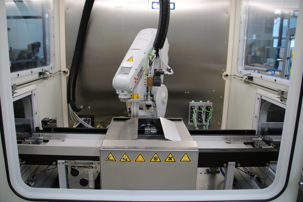
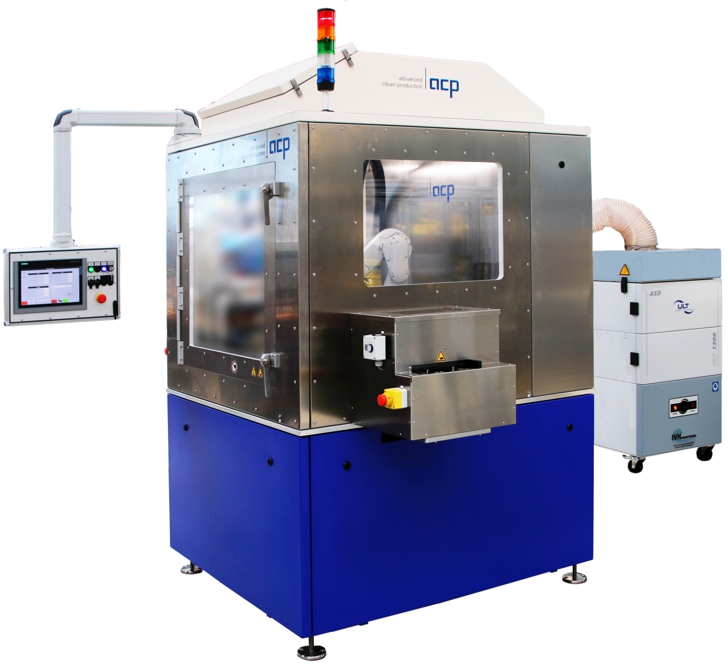
To clean the valve components, acp built the fully-automated Jetcell cleaning system using standardized modules, tailoring it to the application and to the manufacturer's production conditions.
The workpiece carriers are used both for the cleaning step and for the partial PVD coating process. Process parameters, such as the volume flows for compressed air and carbon dioxide, type of jet nozzle, distance of jet away from the part, cleaning time, as well as the motion sequence, are appropriately adapted. This enables the required cycle time of six minutes for cleaning a fully-loaded workpiece carrier with around 150 parts to be met.
To optimally integrate the cleaning system into the existing workflow, buffer that holds five workpiece carriers is located on the input and on the output side. The carriers, which are marked with a digital matrix code to ensure seamless documentation of the cleaning process, are fed one at a time into the cleaning cabin via an appropriately-sized lock. As soon as the lock is closed, the cleaning process starts. Using a specific motion sequence, a robot moves the cleaning unit with jet nozzle over the valve components at a defined distance. A sensor system continuously monitors the consistency of the jet. Once all parts have been cleaned, the lock on the output side opens and the workpiece carrier is advanced to the encapsulated unloading area.
CO2 cleaning in a measuring cell
Indexable inserts, which are manufactured in small quantities with individual geometries and dimensions varying between ten and twenty five millimeters, have extremely tight tolerances that may not exceed one to two micrometers.
To ensure this high accuracy, the entire contour of the carbide parts is measured at the manufacturer's after grinding. Since impurities on the surface from machining residues and grinding dust can cause measurement errors, in the past the inserts were cleaned manually at great expense. The manufacturer wanted to integrate this process into the automated production line.
In this case, a cleaning module was integrated into the measuring cell, which is docked directly to the grinding machine. This solution allows the existing robot to remove the inserts from the grinding machine via a lock, move them in a defined short motion sequence under the snow jet and then set them down neatly in the measuring area. The motion sequences, jet-cleaning times and respective volume flows for the various indexable inserts are all stored in the control system as part-specific programs.
By precisely tailoring the cleaning step to the application and cycle time specifications, as well as being able to operate the system as a stand-alone unit, inline and in interlinked manufacturing environments, the Industry 4.0-capable quattroClean snow jet technology can play a major role when it comes to automating and digitizing production processes.
Standardized interfaces makes it easy to integrate the cleaning system into higher-level host computers and control it via these systems. To ensure seamless documentation and traceability, all process parameters are automatically recorded and transmitted to the host computer.


