Successfully machining truck engine cylinder bores requires teamwork
Successfully machining truck engine cylinder bores requires teamwork
Modern truck engines are produced at the Mercedes-Benz plant in Mannheim, Germany. The requirements for ideal engine properties include extremely tight tolerances for the decisive dimensions of the engine blocks. Thanks to the close cooperation between the specialists from Mercedes-Benz, the machine manufacturer and toolmaker Mapal, significant progress was made when a new production line for machining engine blocks was designed.
Article from Mapal
Modern truck engines are produced at the Mercedes-Benz plant in Mannheim, Germany. The requirements for ideal engine properties include extremely tight tolerances for the decisive dimensions of the engine blocks. Thanks to the close cooperation between the specialists from Mercedes-Benz, the machine manufacturer and toolmaker Mapal, significant progress was made when a new production line for machining engine blocks was designed.
Manufacturing engines requires the highest level of precision. To ensure the best-possible engine properties, the corresponding surfaces in the engine block must be machined with the utmost accuracy. They have a complex geometry and numerous key characteristics for which the highest tolerance classes must be reliably observed. Depending on the engine type, these include multiple H7 fits, various areas with accuracy specifications less than 15 µm, as well as chamfers with tight tolerances, including a 20° chamfer with an outlet, for which an angle tolerance of just ± 0.025° (1' 30") must be observed while meeting the high requirements in terms of surface quality at the same time. Aside from all the accuracy, the focus is also on cost-effective manufacturing.
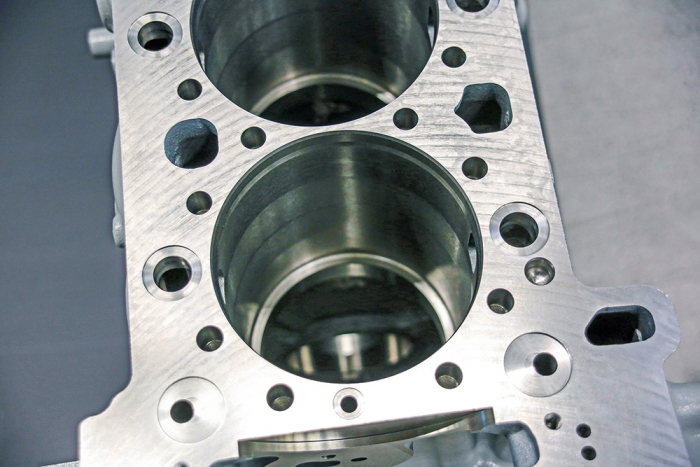
Machining these adapters for the cylinder liners requires high levels of precision.
Only manageable with actuating tools
A first line for machining these engine blocks was commissioned in 2011. When planning a second line, the persons responsible drew on their experience with the first line. They identified the machining of the bores for the cylinder liner adapters as particularly challenging. The machining was divided into two stations: one for premachining and one for fine machining.
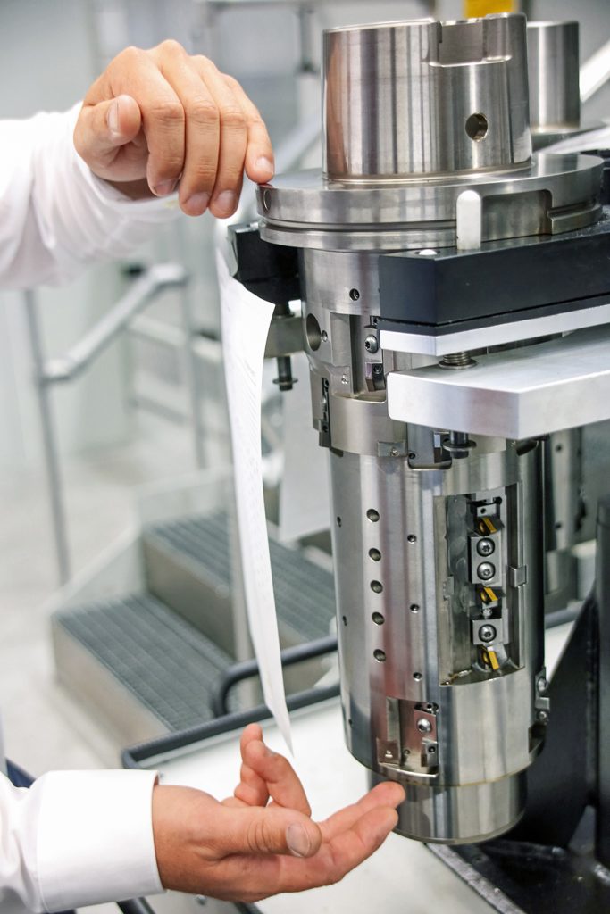
To this end, Mapal has developed complex actuating tools that are equipped with up to 20 indexable inserts, including ISO inserts and custom inserts. The actuating tools feature a tool body in monoblock design. The HSK-160 connection shows an enlarged face surface with a diameter of 200 mm. One tool weighs a total of up to 60 kg.
Despite the connection and a tool length of 380 mm, it must be ensured that the tool has a radial runout accuracy of 3 µm. The slides are actuated by a drawbar via an additional NC axis in the machine controller. It had to be integrated in the HSK connection and suitable for the automatic tool change. This challenge was solved with a high-precision bayonet coupling. It is used to couple the drawbar automatically during a tool change.
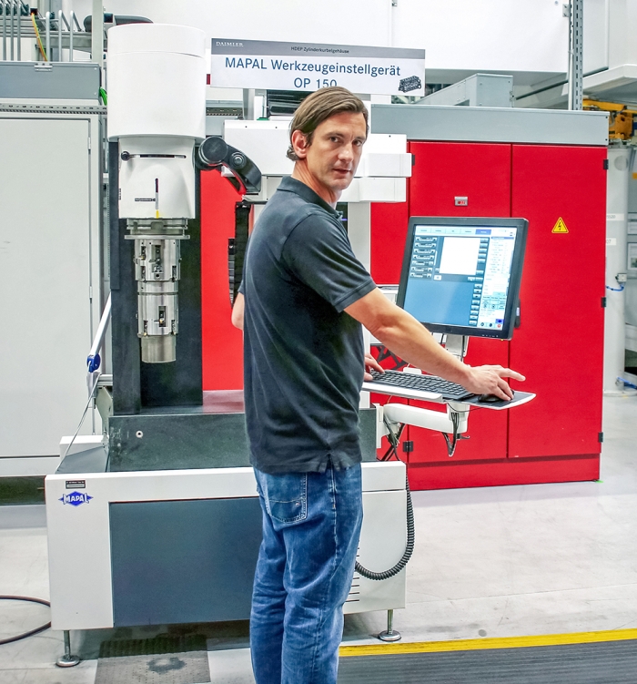
Christoph Wilhelm, Mapal application engineer, works on the measuring and setting a fixture with a hanging tool arrangement developed specially for the application.
Inside the tool, the movements of the drawbar are transferred to the slides by means of carbide ramps. To achieve the required quantities, three bores are machined simultaneously with three spindles. The three tools per machine are each assigned to a particular spindle, thus ensuring process reliability. For each tool, there is a sister tool and a further reserve tool for regular maintenance work and repairs at Mapal.
Given that the tools have to be manufactured with great precision, the amount of manual manufacturing work at Mapal was high. For example, the slide shafts in the tool body were lapped by hand, and the accuracy of the drawbar mechanics had to satisfy the highest requirements in terms of precision. The manual working time for each of these tools alone amounted to multiple man weeks.
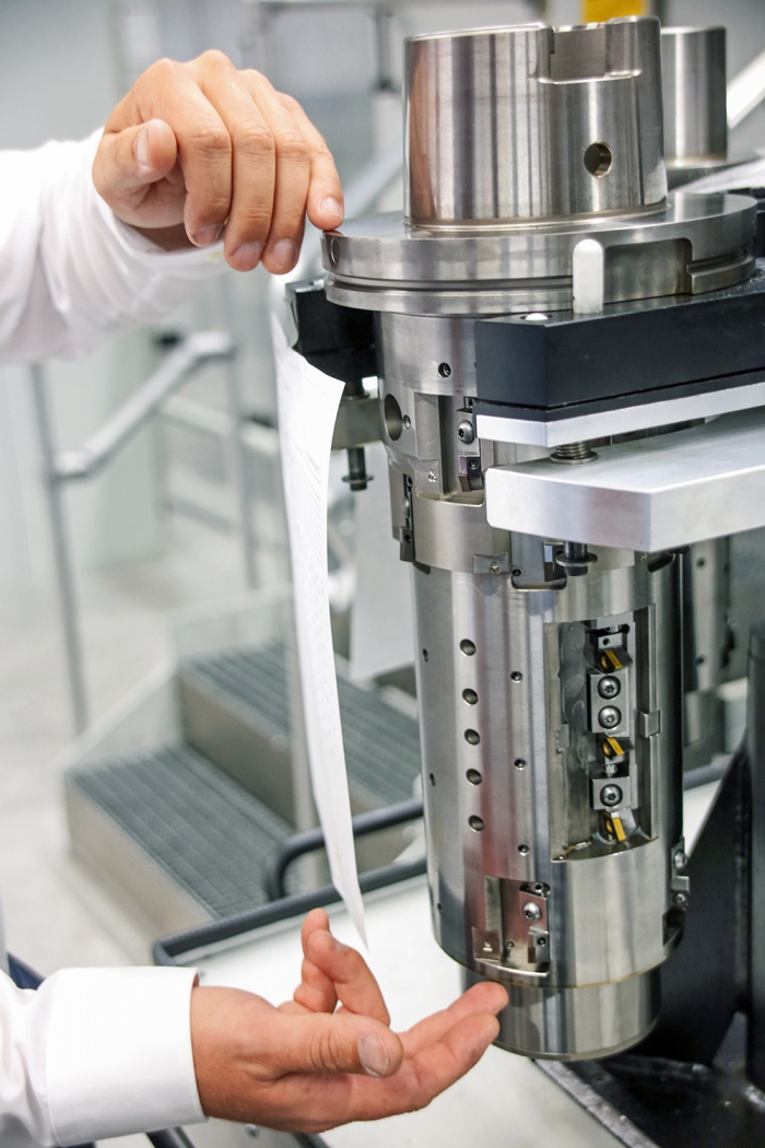
At a length of 380 mm, the runout variation of the tool must not exceed 3 µm.
Replacing the cutting edges and adjusting the tools outside of the machine
With machining operations like these, the cutting edges of such tools are usually replaced and adjusted in the working area of the machine. Due to the cooling lubricant, this is not only uncomfortable for the machine operator, the machine also cannot produce during this time. In three-shift operation and with three tools per machine, this downtime would amount to three to four hours per day.
Together with the employees from Mercedes-Benz and the machine builder, Mapal consequently developed a concept for an automatic tool change and for adjusting the tools outside of the machine. This may sound mundane at first, as this is quite a normal procedure with machining systems. However, the dimensions of the tools alone indicate the extent of the challenge in this case. Given that a machine with an automatic tool change for this type of machining and these dimensions is a world first, the project required a great deal of innovative spirit and the courage to try out new things from all project partners.
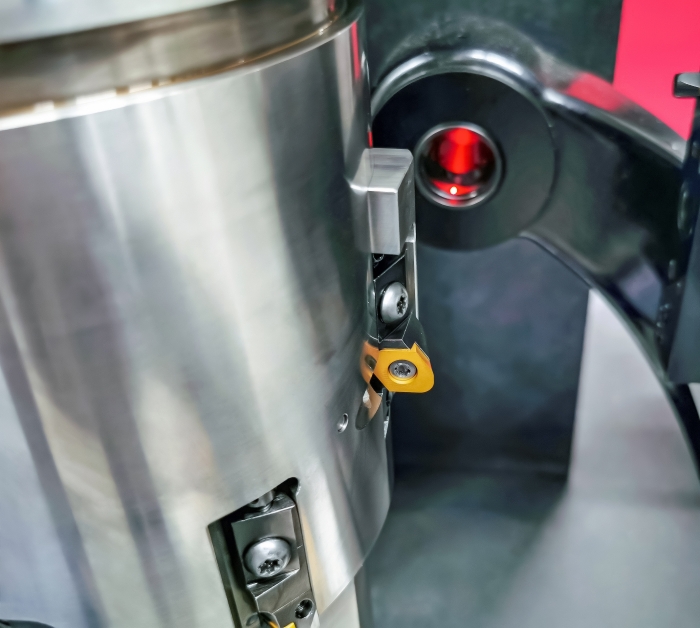
Form-ground inserts with a special contour are used in certain areas of the actuating tool.
Unique setting fixtures for hanging tools
In an effort to ensure that the external adjustment is as simple as possible, Mapal developed the corresponding devices for transporting, adjusting and maintaining the tools. This included a handling solution for inserting and replacing tools in the magazine, as the tools are inserted into the machining system while hanging, which is quite unusual. Due to the high tool weight of around 60 kg, the effort of just "turning over" the tool twice manually would have put the personnel under a lot of strain. When working with such a weight, the safety aspect also plays a major role.
Furthermore, there would have been a risk that the tool could be damaged in the process. This is why Mapal realized two unique setting fixtures into which the tools are inserted in a hanging position. A cart for hanging transport between the machining system and the setting fixture was also developed. The tools are thus transported and adjusted in the same position in which they are used in the machining system.
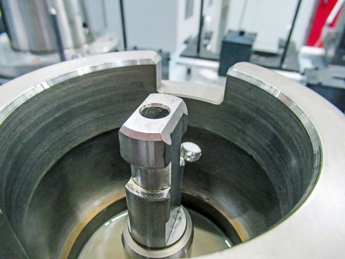
The slides of the actuating tool are actuated via a drawbar with high-precision bayonet coupling.
The measurement results determined on the setting fixtures are transmitted directly to an RFID data medium on the tool. The controller of the machining system reads it out when the tools are inserted. This way, the machine can readjust some of the important measurements using the actuating slides during machining. As from the second workpiece, the results of the routine QA measurement are taken into account. This closed quality control loop for the tools was a high priority for Mercedes-Benz.
Overall, the line was commissioned as planned. The tools fulfil their tasks in accordance with all specifications, and the engine blocks are now manufactured with great precision on the production line.


