Whitepaper: How to automate chip removal with the right conveyor
Whitepaper: How to automate chip removal with the right conveyor
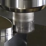
For today's industrial manufacturing applications, it's all about output. The goal is to machine as many parts as possible in the shortest amount of time to maximize profitability. In industries that regularly take huge blocks of metal and machine them down to a part that's approximately 10 to 20 percent of the size and weight of the original piece, that process generates high volumes of metal chips, shavings, grindings and turnings.
For today's industrial manufacturing applications, it's all about output. The goal is to machine as many parts as possible in the shortest amount of time to maximize profitability. In industries that regularly take huge blocks of metal and machine them down to a part that's approximately 10 to 20 percent of the size and weight of the original piece, that process generates high volumes of metal chips, shavings, grindings and turnings.
Gantry mills and other high-speed machining centers can't simply let all that scrap pile up on the manufacturing floor. Manually removing it with shovels isn't (or shouldn't be) a viable option, both for the health and safety risks, as well as the fact that there's more material being generated than human beings can keep up with.
These facilities need automated solutions like conveying systems that are designed to efficiently and expediently move these massive amounts of material out of the cutting machines and the work zone to an area where they can be processed, disposed of or recycled. The coolant used by the cutting machines has to be dealt with as well, and its presence is one of the factors that affects the composition of the scrap material, which in turn dictates the type of conveying equipment that is best suited to move it.
To make an informed decision about a conveying system for metal scrap, it's important to understand how high-speed, high-volume machine shops operate. Most are set up with several large milling machines that typically are 30- to 50-feet long and 10- to 15-feet wide. If you set a 3,000-lb. block of aluminum on each one and reduce it to a 300-lb. part, that leaves 2,700 lbs. of aluminum shavings per part manufactured. That material must be removed from the gantry tables as quickly as possible to ensure effective machining, a clean work area for surface finish, and minimal lag time before the next block is set in place and the process begins again.
Heavy-flow flood coolant is usually used to spray the tool in high-rate applications because it serves a dual purpose: it sends the scrap away from the tool, and more coolant means less heat, which allows for faster cutting and longer tool life. Some shops have considered the option of using less coolant – in which case a vacuum-type system could be used to pull the drier chips off the tool – but that is counterintuitive to most organizations' attempts to get maximum profitability and longevity from their machines. While reduced coolant use does equate to less cost, it typically requires the machining process to be slower, which results in compromised output.
Due to the size of these milling machines and the sheer tonnage of the scrap they generate, there usually is extremely limited space on the floor for the material to accumulate. Factor in the assumed use of flood coolant and it's easy to see why high-rate applications require a multi-faceted conveying solution capable of handling large volumes of scrap and fluid in an efficient, automated fashion that eliminates the safety risks associated with shoveling or sweeping chips and turnings.
There are several conveyor options available, each having advantages and disadvantages depending on the specific high-rate application. The four main factors that should influence any conveying system decision are the type of material, the chip profile, the type of coolant used and the amount of coolant used.
The simplest solution is a steel belt conveyor, which is used in these applications with some regularity.
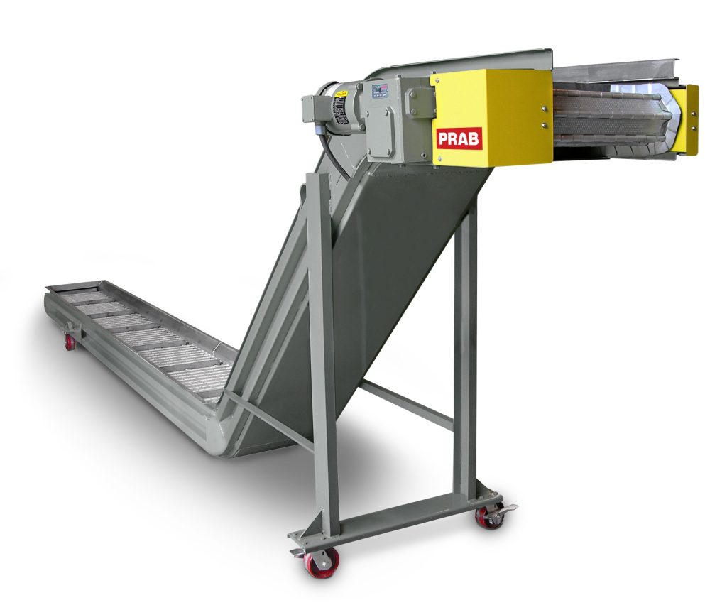
A steel-belt conveyor handles most types of metal scrap. Photos courtesy of PRAB
More versatile than other types of material handling equipment, the steel belt conveyor can handle most types of wet or dry metal scrap – from bushy material to chips and turnings – in any volume, and in a wide variety of conveyor paths.
A hinged steel belt is the industry standard, but different types of belts can be used in these conveyors depending on the application, including:
Beaded Pan – for high heat and heavy wear applications
Pivot Belt – for small, thin chips and sticky scrap
Bucket Belt – for conveying highly flowable product up a steep incline
Steel belt conveyors can move a high volume of material consistently, even in piles and high surges, but they aren't the best solution for dealing with high volumes of liquid flow. They also have a lot of moving parts that wear quickly and require maintenance when chips and fine particulate enter the mechanism.
The next option is a drag conveyor, designed for conveying and elevating the most difficult, most abrasive, wet or dry materials in severe-duty situations. These conveyors can be installed at floor level for easy transfer of material from the machine table to the conveyor. They also feature multiple infeed and discharge points to fit specific applications, and they can be customized with coolant pumps for integration with a chip and fluid filtration system.
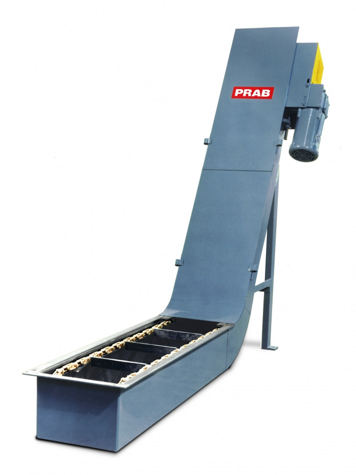
A drag conveyor is suitable for severe-duty situations.
Compared to steel belt conveyors, drag conveyors can handle a higher volume of coolant, and they have fewer moving parts to deliver more consistent material flow as opposed to surge loading. They are not ideal for processes that send cutoffs, bar ends, tooling pieces and other solid materials or parts through the conveyor, and they are not conducive to moving longer, stringier drill chips or turnings that can twist up and bundle.
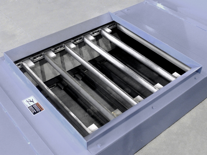
Trough-type conveyors are workhorses that transfer all types of metal chips, fines and turnings, wet or dry bushy wads, and tramp metal solids with time- and energy-saving efficiency. Their liquid-tight trough construction makes them ideal for high-volume coolant flow applications, and their flush-with-the-floor orientation allows both material and coolant to run directly into the conveyor with minimal manual interaction or slowdown of the process.
These conveyors are available in two types, each a reciprocating ram type of conveyor. A Harpoon trough conveyor has a ram assembly that floats in the trough and reciprocates back and forth. These troughs can collect high volumes of turnings, chips, stringies and as much fluid as is required. They can even pass small chunks of solid material that end up in the trough.
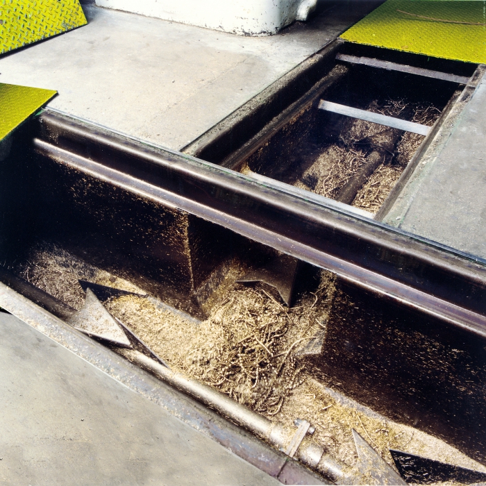
A Harpoon trough conveyor has a ram assembly that floats in the trough and reciprocates back and forth.
While this conveyance method is a little slower than others, a Harpoon trough can move a higher volume of material, so it can accomplish the same results as a faster-moving conveyor. Component wear can be a concern with these conveyors due to metal-on-metal contact on the bottom of the trough as the ram assembly reciprocates.
To combat this issue, the Push-Bar trough conveyor was developed. In this type of conveyor, the ram assembly is mounted on a bushing and rail system that lifts it off the bottom of the trough. This allows fluid and fine particulate to flow through the conveyor along the bottom of the trough without the excess wear.
In applications where there is a lot of fine particulate moving through the conveyor, the Harpoon system may be preferable because it scrapes along the bottom of the trough and will do a more thorough job of cleaning out the particulate. In a Push-Bar system, because the ram assembly is suspended slightly above the bottom of the trough, there will always be some amount of material there.
Automating the chip removal process is a must for metalworking operations with high Q rates. By using conveyors to quickly transfer scrap and coolant from tooling machines to a central collection area for separation and processing, machine shops can produce more parts with less downtime between jobs, create more value for their scrap, and increase revenue by recycling coolant. Not all conveying systems are suited for every scrap-handling application, however. Taking the time to understand and asses the advantages and disadvantages of each available system as they apply to your operation – ideally with the input of a trusted, experienced supplier – will help you select the best solution for your specific needs and bring the greatest return on your investment.


