All images courtesy of CNC Software
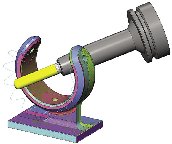
Simulation provides an accurate 3-D visual representation of the amount of stock removed from a virtual workpiece at any stage of the cutting process.
achine shops of all sizes are purchasing record numbers of 5-axis CNC machines, and for good reason. These machines enable single-setup manufacturing strategies, which are much more productive than conventional machining using several pieces of equipment. Keeping manufacturing all in one setup also eliminates stack-up errors and resulting scrap.
In addition, many advanced, complex part designs are impossible to produce on anything but a 5-axis machine. To quote those parts, shops must invest in the equipment, and prices for reasonably accurate 5-axis systems have dropped significantly.
Along with the many opportunities 5-axis machining creates, there are substantial risks. Five-axis CNC programs are geometrically more complex than 3-axis programs, which can create more opportunities to damage cutting tools, toolholders, equipment and the part itself via a crash. For example, if a shop has hundreds of hours invested in a complex piece made from a single piece of stock, a crash would be extremely costly.
On the other hand, time on a 5-axis machine is far too valuable to be wasted by having operators hover over the machine as it cycles through its operations to verify they are safe and correct. This is especially true for small runs.
With so much to gain—and lose—various forms of machine simulation have become the 5-axis CNC programmer’s constant companion. Simulation is the first line of defense against damage and lost productivity. It also gives the programmer additional tools to solve fixture-design-for-manufacturability challenges and make parts more productively. Manufacturers that have previously not used their CAM systems’ simulation capabilities often become converts as soon as they install their first 5-axis machine. They are frequently surprised at the depth of simulation resources provided.
Program Simulation
High-end CAM software has built-in simulation capabilities that allow programmers to ascertain that the program they have written will perform cutting operations exactly as they had in mind when they wrote them. The software typically includes the following features.
Backplot simulation.Almost every CAM programmer relies on backplotting—on-screen geometrical “tracing” of the contact point—to visualize tool movement through various CNC manufacturing operations. Backplotting provides fast, visual confirmation that a tool is performing the desired cutting operations in the most efficient sequence. As the backplot simulation progresses, information about the tool choices appears in a separate window. Backplot simulation serves as a sequential template for checking the appropriateness of tools and settings at each stage of the process.
The backplot simulation also generates a close approximation of machining time not including tool-change time. This can be invaluable for estimating costs, especially when they involve CNC cutting programs that will run for many hours, if not days.
If the programmer and machinist are different people, conferring over the backplot simulation helps them get on the same page. The machinist will have a clearer understanding of how he should set up and run a process and the programmer can confirm that the strategies he has chosen are appropriate for the equipment and shop conditions.
Stock-removal simulation.This type of simulation provides an accurate 3-D visual representation of the amount of stock removed from a virtual workpiece at any stage of the cutting process. This representation may be color-coded to indicate that material removal falls within the specification or may automatically highlight areas where too much or too little material has been removed. Skilled 5-axis programmers frequently run the stock-removal simulation at high speed, as if it were time-lapse photography, dynamically zooming in and out of areas of concern on the fly.
Those who program 5-axis machines find themselves using backplot, verify and full-blown machine simulation after programming every operation. This makes them better programmers because they quickly learn what will and won’t work. It also gives them powerful tools that allow for safe experimentation with different manufacturing strategies. Used this way, machine simulation is the safest, most-effective way to create effective and efficient production methods.
Beyond the Basics
Simulation may be used to effectively prove out the manufacturing process for individual parts, as well as the whole manufacturing process cycle of a work cell as parts move from machine to machine. When better strategies are discovered via simulation, they frequently become part of a manufacturer’s mix of proprietary competitive advantages. The following are some advanced features of simulation programs.
Finite element analysis.FEA is not actually a CAM software feature but is offered by some software vendors that create CAD models. Ideally, the CAD and CAM software packages are so tightly integrated that the design and manufacturing engineers can work back and forth with each other to concurrently modify and improve design elements and manufacturing strategies. When design and manufacturing strategies are developed concurrently, FEA can determine if the changes made to improve manufacturability will not only meet part specifications but also determine that the stresses generated during manufacturing will not damage the product, tools, fixtures or machine.
Full machine simulation of an insulator bracket being cut (see close-up below).
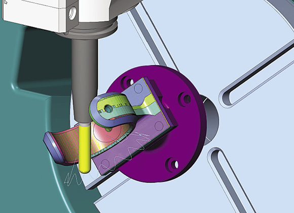
Close-up of the insulator bracket being cut during simulation. The programmer is checking “oscillation” motion to prolong tool life.
Surface finish inspection. Inspecting critical surfaces via stock-removal simulation at high magnification provides an accurate visualization of the surface finish that will be imparted. Most nicks and scratches produced by awkward tool movements actually appear in a magnified simulation. A manufacturer of injection tooling for micromolded medical parts, for instance, said this approach to verification is like taking an EDM tool the size of a pea and blowing it up to the size of a basketball to find critical surface imperfections.
Chamfering visualization. Many 5-axis parts are used in high-precision assemblies and, therefore, must not have any cosmetic defects that could compromise the durability or performance of wear surfaces. For these parts, chamfering may be used extensively to eliminate the need for costly secondary deburring operations. In this case, both backplot and stock-removal simulations ensure that the tools can get into tight spaces without crashing and that chamfering does indeed produce the desired effect. Verification at high magnification can show if chamfering removes potentially abrasive nicks and burrs.
Safe tool entries and exits. Backplot simulation shows if a tool is getting dangerously close to or hitting impinging surfaces. It is possible to specify precise entry and exit curves during toolpath creation, but a manufacturer of aerospace parts takes this process one step further. He uses the CAM software’s “save as geometry feature” to turn his backplot into an exact representation of the problematic cut’s location. Then he adds geometry to follow for safe tool entry and exit at the beginning and end of the operation. This allows him to navigate a tool into and out of confined areas without damaging nearby surfaces.
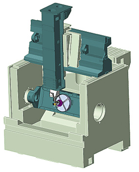
Machine Simulation
In the 5-axis world, it is sometimes necessary not only to simulate the CAM software’s intermediate code but also the G code driving specific, individual machines with unique kinematics. This higher level of verification, known as machine simulation, proves out machining strategies in a virtual 5-axis environment that ensures part geometries, tools, fixtures and machine components will not interfere with each other during the cutting process.
There are two varieties of machine simulation. The first takes the intermediate code (APT, NCI, CLS) generated by the CAM system prior to post-processing into G code for the machine’s control and uses that code to drive a virtual replica of the specific 5-axis machine. A small number of CAM developers have taken this approach, with some even refining it to the point where a separate, simplified stream of code is generated to drive the 5-axis machine simulation process.
The second, even more meticulous approach drives a precise virtual replica via the G code generated by a CAM system’s post-processor. This program allows the user to choose from a variety of machine and control options and effectively simulates any G-code language.
The good news is that either of these approaches will accurately simulate machine behavior if an accurate model of the machine has been created and the simulation program has been properly configured. Correctly configuring a virtual replica and the simulation process requires an in-depth knowledge of the specific 5-axis machine, simulation software and post-processor.
Setting up an effective machine simulation program can be time consuming and expensive, but it will protect a 5-axis CNC machine investment and dramatically improve the manufacturing process. The alternative is to laboriously step through first-piece manufacturing operations sequentially at the machine, wasting machine time and labor—unacceptable in today’s manufacturing environment. Simulation also provides a safe, relatively low-cost virtual environment for testing competing “what if” scenarios, so simulation-derived, 5-axis machining strategies can become a competitive advantage.
For those who have purchased or are about to purchase 5-axis CNC equipment, simulation is or will soon become a core competency. It’s not a question of if but when. Manufacturers that have embraced and cultivate 5-axis simulation skills early can take advantage of their constant companion. CTE
Related Glossary Terms
- 3-D
3-D
Way of displaying real-world objects in a natural way by showing depth, height and width. This system uses the X, Y and Z axes.
- abrasive
abrasive
Substance used for grinding, honing, lapping, superfinishing and polishing. Examples include garnet, emery, corundum, silicon carbide, cubic boron nitride and diamond in various grit sizes.
- chamfering
chamfering
Machining a bevel on a workpiece or tool; improves a tool’s entrance into the cut.
- computer numerical control ( CNC)
computer numerical control ( CNC)
Microprocessor-based controller dedicated to a machine tool that permits the creation or modification of parts. Programmed numerical control activates the machine’s servos and spindle drives and controls the various machining operations. See DNC, direct numerical control; NC, numerical control.
- computer-aided design ( CAD)
computer-aided design ( CAD)
Product-design functions performed with the help of computers and special software.
- computer-aided manufacturing ( CAM)
computer-aided manufacturing ( CAM)
Use of computers to control machining and manufacturing processes.
- electrical-discharge machining ( EDM)
electrical-discharge machining ( EDM)
Process that vaporizes conductive materials by controlled application of pulsed electrical current that flows between a workpiece and electrode (tool) in a dielectric fluid. Permits machining shapes to tight accuracies without the internal stresses conventional machining often generates. Useful in diemaking.
- toolpath( cutter path)
toolpath( cutter path)
2-D or 3-D path generated by program code or a CAM system and followed by tool when machining a part.


