It seems that with every new model of CNC lathe or mill, machine controllers get a little quicker and a whole lot smarter. Maybe they haven’t yet achieved HAL 9000 intelligence, but new controls and servosystems process data faster, enable tools to corner more quickly and simultaneously manage more axes than ever before. Some are even capable of monitoring conditions in the machine and adjusting cutting parameters accordingly. It’s like having a virtual machinist with his hand on the feed rate override.
The concept, at least, is nothing new. A 1989 white paper by the American Society of Mechanical Engineers mentioned that Bendix Corp. was researching adaptive-control (AC) optimization as early as 1962. The paper stated that formidable challenges to commercialization of AC technology still existed, including development of reliable sensors, machine tool designs that take into consideration AC requirements and development of stable AC strategies.
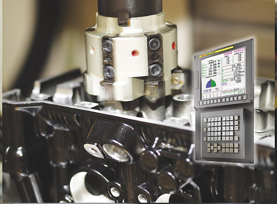
Courtesy of FANUC America
Intermittent loads, such those that occur when machining this cylinder head, are excellent applications for adaptive control technology, which decreases cycle time by increasing feed rates though areas of light metal removal.
Many of the goals of that Reagan Administration-era paper have been met. Laser cutting machines automatically adjust gas and power outputs, EDMs regulate their own sparks and turning and other machining centers slow down or stop when cutters become dull. The pinnacle of AC technology—and something few controls are actually capable of—is the ability to increase feeds faster than programmed when conditions permit, thus autonomously increasing part output.
Watch Those Corners
“There are two basic types of adaptive control technology,” said Thomas Pleuger, account manager for control manufacturer Mitsubishi Electric Automation Inc., Vernon Hills, Ill. “One is look-ahead technology, which relies on a high-gain servocontrol to achieve smooth acceleration and deceleration during changes in machine direction. And then there are adaptive control products that sense spindle load and adjust programmed feed rates up or down according to a set of predefined parameters.”
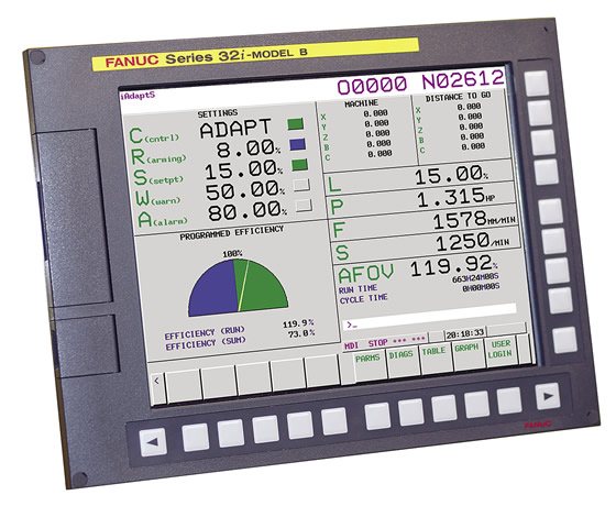
Courtesy of FANUC America
FANUC’s iAdaptS AC option on a 32i control.
Look-ahead is what keeps your machining center from vibrating across the floor during tight profiling operations. It also prevents the machine from overshooting a given set of coordinates, thus ensuring part accuracy. It’s even possible to tune the AC based on specific application requirements, configuring it so optimal cutting conditions are achieved across a range of machining demands. “Tearing through massive amounts of material quickly requires greater latitude in terms of in-position checking, whereas high-speed contouring in a mold application means tuning for optimal machine response,” Pleuger said. “Each of these can be accommodated through a series of parameters in the control system.”
This tuning can be carried to a high level. Consider cross-drilling on a mill/turn center. Pleuger explained that many of Mitsubishi’s controls (and some of its competitors’ products as well) can monitor servoload in the cut and kill the machining cycle if a certain threshold is exceeded. Likewise, by keeping a virtual eye on ballscrew temperatures, an AC can dynamically compensate for thermal growth
“We don’t offer an out-of-the-box solution to speed up or slow down the machine based on how much material you’re removing, but we do have robust control logic that maintains speed and accuracy automatically,” he said. “If you need more than that, tools are available to develop such solutions, or, alternately, there are several third-party solutions available.”
Dithering Around
One company offering a standard AC package is FANUC America Corp., Hoffman Estates, Ill. As Engineering Manager Paul Webster explained, FANUC’s iAdaptS AC option for its controls decreases roughing times by sensing spindle loads and increasing programmed feed rates where possible. “The current draw at the spindle motor is directly proportional to the cutting load. By constantly monitoring that current, we can compare its value to a predetermined range, adjusting the feed rate up or down accordingly.”
According to the company, iAdaptS reduces cycle times up to 40 percent and compensates for variations in material hardness, tool wear and DOC. Once installed, the only requirement is teaching the AC what to expect. This is done one tool at a time, for a maxi- mum of 64 tools in the library. Webster said the learning process is no big deal. “You basically run the tool once in teach mode, then set realistic values on how much that tool is allowed to speed up or slow down from the programmed feed rate.”
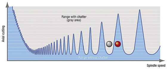
Courtesy of Okuma America
Keeping an eye on chatter, Okuma’s Machining Navi option adjusts spindle speed to break harmonics during cutting, so machining is performed in a range that doesn’t cause chatter, as shown on this stability lobe diagram.
It’s not a cure-all, Webster pointed out, because the AC primarily protects the cutters and reduces cycle time during operations with heavier cutting loads, such as when roughing. So, for example, don’t expect to monitor the load from a 1⁄8 "-dia. cutter mounted in a 40-hp spindle.
Still, the iAdaptS is a no-brainer in terms of cost, with a list price of about $1,100. Better yet, it also works on older FANUC controls all the way back to the 16i and 18i series, Webster said.
Another advantage of iAdaptS is a feature called dithering. One issue with dynamically adjusting feed rates is that doing so can create a feedback loop, or resonance, leading to uncontrolled axis movement and broken tools. FANUC gets around this problem by slightly varying the set feed rate (dithering), which cancels the resonance. “If you’ve ever seen an operator tweaking the feed rate override to kill chatter, it’s similar to that,” he said.
Chatter is another problem solved by adaptive control technology. Director of Technology Brian Sides of Okuma America Corp., Charlotte, N.C., noted the company’s “Machining Navi” option is one solution.
“There are two flavors to this,” he said. “During machining, Navi M-g uses a microphone to listen for chatter and recommends a range of spindle speeds to eliminate it. The Navi M-i option uses vibration sensors in the spindle and automatically optimizes the spindle rpm in real time.”
Sides said there is also a Machining Navi version for lathes, which uses G code to break harmonics that lead to chatter. When executed during setup, the control commands the spindle to rotate in alternating directions. This determines the inertial qualities of the part setup and, when activated during cutting, oscillates the spindle speed to break the harmonics that lead to chatter.
Old Dogs, New Tricks
Okuma’s THINC control offers a number of other whiz-bang adaptive features, including thermal compensation and kinematic error correction, but when it comes to adaptive feed rate control, Sides will send you to the Pine Tree State. “We rely on Caron in Maine for this,” he said. “They are the best in class when it comes to monitoring horsepower and adjusting feed rate based on that.”
That’s good news for Rob Caron, president of Caron Engineering Inc., Wells, Maine, which developed TMAC (Tool Monitor Adaptive Control). Similar in concept to the FANUC iAdaptS design, TMAC monitors spindle load and uses those measurements to adjust the axial feed rate up or down based on cutting conditions. And, like iAdaptS, TMAC uses a teach function to establish expected operating parameters.
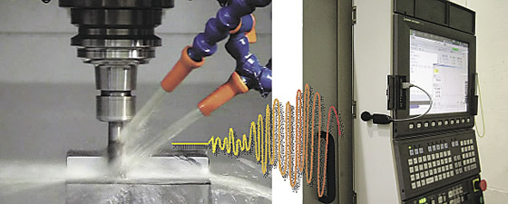
Courtesy of Okuma America
Machining Navi listens to cutting tools and tells the controller to adjust cutting speed accordingly.
The similarities end there, however. Where FANUC focuses on reducing cycle time and improving tool life when roughing, TMAC is advertised as suitable for even the lightest cuts. Caron offered some examples: “On a 20-hp spindle running at 40,000 rpm, we can monitor a 1mm-dia. cutting tool. With a 50-hp spindle, we’ll monitor tools down to 1⁄8" in diameter.”
It manages this feat through feedback from a special sensor mounted in the spindle, which measures current and voltage. When multiplied, these values indicate true horsepower consumption, Caron explained, which lets TMAC accommodate various machining conditions, increasing feed rate where possible, backing off when necessary and signaling the machine when it’s time to replace a cutting tool.
Best of all, TMAC is control-agnostic. It can also be used with multifunctional machines such as Swiss-style lathes and mill/turn centers, monitoring several processes simultaneously.
“We work with most of the builders and can retrofit most machines, dating as far back as the mid-’80s,” Caron said. That doesn’t imply TMAC, which costs around $15,000 per machine, is appropriate for an old clunker. Because of the increased performance that ACs bring to the table, any machine tool targeted for supercharging with AC technology should be mechanically sound.
Lightly or unattended machining operations are good target areas for TMAC, as are operations with long process times, such as moldmaking and 3D surfacing of complex shapes. Castings and forgings are another key application area due to the inconsistent levels of material removal during roughing.
In one sense, AC replaces what machinists have been doing for years when they stand in front of a machine and tweak feed rates based on sound and feel. The difference is that adaptive controls do it much faster, more accurately and don’t need a coffee break. This frees up machinists to do more important tasks than babysit machines, and gives shop owners a boost to the bottom line. CTE
Cashing in your chips
Don’t have the cash for an adaptive control? Ken Merritt, senior applications engineer for SolidCAM Inc., Deltona, Fla., says it might be unnecessary.
“Traditional toolpaths utilize racetrack-style offsets from the part profile,” he said. “These create what I call compression zones, where the change in direction results in the tool being significantly over engaged.”
Merritt explained that an AC compensates for this by reducing the programmed feed rate, but it’s better to eliminate these spikes in tool load altogether. “SolidCAM utilizes a morphing spiral process as part of its toolpath algorithm, the tool is never overloaded. This greatly increases tool life while substantially reducing cycle time,” he said.
As proof, Merritt described his work with a local Hurco machine tool representative to improve the process time on a demo for a vertical machining center at a trade show. He said: “We reprogrammed the machine using our software. The cycle time went from 46 minutes to around 8½ minutes. It was pretty impressive.”
Not to be outdone, the rep used Hurco’s UltiMotion adaptive control, which reportedly reduces cycle time by evaluating each section of the toolpath to maximize look-ahead. In this case, the AC reduced cycle time an additional 25 percent, to 6 minutes, 38 seconds.
The trick, Merritt said, is controlling chip thinning, which occurs as the cutting angle decreases. By increasing the feed rate, a constant chip load and thickness is maintained. “Our feed rate is variable throughout the entire toolpath.”
The downside is that older or less-capable machines may not keep up. As Merritt explained, AC helps achieve high-performance toolpaths by improving look-ahead and acceleration/deceleration in corners. “I’m not offering names, but we have seen how you can program some commodity machines at 200 ipm but only achieve half that. It’s only when you get to high-end machine tools with responsive control systems that programmed feed rates are actually attained.”
Merritt added that SolidCAM’s patented morphing technology makes any reliable machine run significantly faster. Add a high-quality servosystem and serious chipmaking results.
—K. Hanson
Contributors
Caron Engineering Inc.
(207) 646-6071
www.caroneng.com
FANUC America Corp.
(888) 326-8287
www.fanucamerica.com
Mitsubishi Electric Automation Inc.
(847) 478-2100
www.meau.com
Okuma America Corp.
(704) 588-7000
www.okuma.com
SolidCAM Inc.
(866) 975-1115
www.solidcam.com
Related Glossary Terms
- backing
backing
1. Flexible portion of a bandsaw blade. 2. Support material behind the cutting edge of a tool. 3. Base material for coated abrasives.
- centers
centers
Cone-shaped pins that support a workpiece by one or two ends during machining. The centers fit into holes drilled in the workpiece ends. Centers that turn with the workpiece are called “live” centers; those that do not are called “dead” centers.
- chatter
chatter
Condition of vibration involving the machine, workpiece and cutting tool. Once this condition arises, it is often self-sustaining until the problem is corrected. Chatter can be identified when lines or grooves appear at regular intervals in the workpiece. These lines or grooves are caused by the teeth of the cutter as they vibrate in and out of the workpiece and their spacing depends on the frequency of vibration.
- computer numerical control ( CNC)
computer numerical control ( CNC)
Microprocessor-based controller dedicated to a machine tool that permits the creation or modification of parts. Programmed numerical control activates the machine’s servos and spindle drives and controls the various machining operations. See DNC, direct numerical control; NC, numerical control.
- cutting speed
cutting speed
Tangential velocity on the surface of the tool or workpiece at the cutting interface. The formula for cutting speed (sfm) is tool diameter 5 0.26 5 spindle speed (rpm). The formula for feed per tooth (fpt) is table feed (ipm)/number of flutes/spindle speed (rpm). The formula for spindle speed (rpm) is cutting speed (sfm) 5 3.82/tool diameter. The formula for table feed (ipm) is feed per tooth (ftp) 5 number of tool flutes 5 spindle speed (rpm).
- feed
feed
Rate of change of position of the tool as a whole, relative to the workpiece while cutting.
- hardness
hardness
Hardness is a measure of the resistance of a material to surface indentation or abrasion. There is no absolute scale for hardness. In order to express hardness quantitatively, each type of test has its own scale, which defines hardness. Indentation hardness obtained through static methods is measured by Brinell, Rockwell, Vickers and Knoop tests. Hardness without indentation is measured by a dynamic method, known as the Scleroscope test.
- inches per minute ( ipm)
inches per minute ( ipm)
Value that refers to how far the workpiece or cutter advances linearly in 1 minute, defined as: ipm = ipt 5 number of effective teeth 5 rpm. Also known as the table feed or machine feed.
- lathe
lathe
Turning machine capable of sawing, milling, grinding, gear-cutting, drilling, reaming, boring, threading, facing, chamfering, grooving, knurling, spinning, parting, necking, taper-cutting, and cam- and eccentric-cutting, as well as step- and straight-turning. Comes in a variety of forms, ranging from manual to semiautomatic to fully automatic, with major types being engine lathes, turning and contouring lathes, turret lathes and numerical-control lathes. The engine lathe consists of a headstock and spindle, tailstock, bed, carriage (complete with apron) and cross slides. Features include gear- (speed) and feed-selector levers, toolpost, compound rest, lead screw and reversing lead screw, threading dial and rapid-traverse lever. Special lathe types include through-the-spindle, camshaft and crankshaft, brake drum and rotor, spinning and gun-barrel machines. Toolroom and bench lathes are used for precision work; the former for tool-and-die work and similar tasks, the latter for small workpieces (instruments, watches), normally without a power feed. Models are typically designated according to their “swing,” or the largest-diameter workpiece that can be rotated; bed length, or the distance between centers; and horsepower generated. See turning machine.
- look-ahead
look-ahead
CNC feature that evaluates many data blocks ahead of the cutting tool’s location to adjust the machining parameters to prevent gouges. This occurs when the feed rate is too high to stop the cutting tool within the required distance, resulting in an overshoot of the tool’s projected path. Ideally, look-ahead should be dynamic, varying the distance and number of program blocks based on the part profile and the desired feed rate.
- machining center
machining center
CNC machine tool capable of drilling, reaming, tapping, milling and boring. Normally comes with an automatic toolchanger. See automatic toolchanger.
- milling machine ( mill)
milling machine ( mill)
Runs endmills and arbor-mounted milling cutters. Features include a head with a spindle that drives the cutters; a column, knee and table that provide motion in the three Cartesian axes; and a base that supports the components and houses the cutting-fluid pump and reservoir. The work is mounted on the table and fed into the rotating cutter or endmill to accomplish the milling steps; vertical milling machines also feed endmills into the work by means of a spindle-mounted quill. Models range from small manual machines to big bed-type and duplex mills. All take one of three basic forms: vertical, horizontal or convertible horizontal/vertical. Vertical machines may be knee-type (the table is mounted on a knee that can be elevated) or bed-type (the table is securely supported and only moves horizontally). In general, horizontal machines are bigger and more powerful, while vertical machines are lighter but more versatile and easier to set up and operate.
- profiling
profiling
Machining vertical edges of workpieces having irregular contours; normally performed with an endmill in a vertical spindle on a milling machine or with a profiler, following a pattern. See mill, milling machine.
- servocontrol
servocontrol
Refers to control of motion. Applied to the industrial robot, it describes automatic feedback, or “closed-loop,” operation in which sensing devices monitor movement and report any deviation between commands as issued and movement as monitored. Deviations trigger corrective action. Robots without servocontrol may be “open-loop” but most often are controlled by preset mechanical or electric stop-switches. Because they are not self-correcting, they have limited capabilities.
- toolpath( cutter path)
toolpath( cutter path)
2-D or 3-D path generated by program code or a CAM system and followed by tool when machining a part.
- turning
turning
Workpiece is held in a chuck, mounted on a face plate or secured between centers and rotated while a cutting tool, normally a single-point tool, is fed into it along its periphery or across its end or face. Takes the form of straight turning (cutting along the periphery of the workpiece); taper turning (creating a taper); step turning (turning different-size diameters on the same work); chamfering (beveling an edge or shoulder); facing (cutting on an end); turning threads (usually external but can be internal); roughing (high-volume metal removal); and finishing (final light cuts). Performed on lathes, turning centers, chucking machines, automatic screw machines and similar machines.
Author

Kip Hanson is a contributing editor for Cutting Tool Engineering magazine. Contact him by phone at (520) 548-7328 or via e-mail at [email protected].


