Several situations in the last few months made me realize cutting speed calculations are not always well understood. However, knowing this information allows metalworking professionals build a base of knowledge that can enable shops to machine more efficiently. In last month’s column, I discussed the basics of understanding cutting equations. In this column, I’ll examine how understanding relationships among the variables can lead to significant efficiency gains.
Cutting tool manufacturers recommend ranges of cutting speeds and chip loads for their products based on testing and experience. More often than not, these values are accurate, but the ranges can vary a lot. It is common for manufacturing engineers and machinists to adjust cutting parameters while developing a machining process. Once they have determined the optimal cutting speed and feed rate for a workpiece material, this information is available for recall when similar applications arise. This eliminates the need for experimentation, resulting in faster development times.
Most if not all CAM packages offer some sort of tool library that allows the programmer to set up different cutting tools and cutting speeds for each type of material. Cutting speed calculations must be understood so the programmer, engineer or machinist can convert the rpm and feed rate values from the machine into information the software can use, which is usually in sfm and chip load per tooth.
With accurate information collected from the shop floor, the programmer can deliver programs that require minimal adjustment. These programs, when coupled with quick-change workholders and probing routines, enable shops to profitably run small jobs.

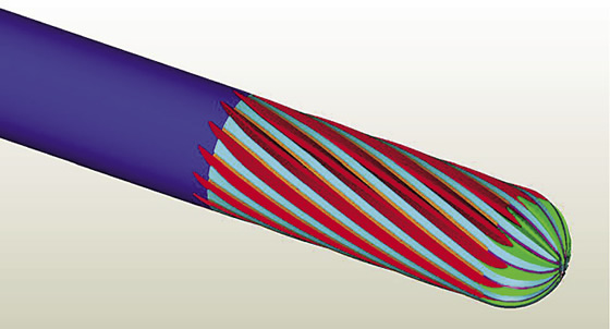
Part manufacturers can increase feed rates when applying tools with a high number of flutes.
I have previously discussed the importance of managing tool wear and how proper management of cutting tools can significantly impact tooling costs. Cutting speed is the most significant factor in managing tool wear. As cutting speed increases, tool life decreases. In a controlled environment, it is possible to predict how an increased cutting speed will influence tool life. The ability to accurately predict tool life improves decision making when attempting to reduce cycle times. Nonetheless, increasing the cutting speed might reduce cycle time but increase overall costs by reducing the life of expensive high-performance tools.
When attempting to reduce cycle time, the first reaction is often to increase the cutting speed and feed rate. According to the feed rate formula (rpm × no. of cutting edges × chip load = ipm), an increase in rpm while maintaining the chip load yields a faster feed rate, which means the machine gets a part done faster.
Getting done faster is good, as long as the tool isn’t already being run at its limit and the increase would cause catastrophic tool failure. Understanding the relationship between cutting speed and chip load can allow shops to creatively approach cycle-time improvements and circumvent these failures.
For example, when applying a 4-flute, ½" endmill at 500 sfm and a chip load of 0.004 ipr to machine a circle with a circumference of 18.84" (6" in diameter), and using the equation of rpm = sfm ÷ diameter × 3.82 and the equation previously provided for feed rate, the following values are generated: 3,820 rpm and 61.1 ipm. Therefore, it takes 18.53 seconds to cut the circle.
If a 6-flute tool with the same parameters is used instead, the following values are generated: 3,820 rpm and 91.68 ipm. This reduces cut time for the circle to 12.35 seconds.
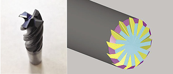
A ½" endmill (left) makes a shallow cut while exhibiting unfavorable tool life, and cycle time requirements do not allow a reduction in cutting speed as it would reduce the feed rate. The tool on the right solves the problem, because the design allows a 60 percent reduction in cutting speed and a 4-ipm increase in the feed rate. This significantly increases tool life while slightly reducing the cycle time.
Besides the cycle-time reduction, another important consideration is the improvement in tool life. In this example, the volume of material being removed doesn’t change because the DOC isn’t altered. Because the volume of material removed is constant, tool life would increase because the work is being distributed over six cutting edges instead of four.
Sometimes it is not possible to add a new tool to solve a production problem. Let’s say the production manager needs a 3-second improvement in cycle time from 18.53 to 15.53 seconds, or 0.259 minutes. Because it is not always possible to just increase the rpm to achieve the savings, work backwards to find possible solutions. Consider the earlier example with a 4-flute endmill cutting a 18.84 " circumference (6 " circle). The following equation calculates the chip load needed to achieve the desired savings: distance (circumference) ÷ time = feed rate.
With the new feed rate determined, calculate the chip load increase to see if it is inside the operating parameters of the tool. In our example, a feed of 72.74 ipm (18.84 circumference ÷ 0.259 minutes) is needed to achieve the desired savings. This requires increasing the chip load to 0.0046 ipt. The toolmaker’s reference material or experience determines if the increase would be detrimental to the tool.
Once familiar with the concept of cutting speed and chip load, it is easy to recognize inefficient machining processes. When addressing tooling issues in a shop, I first calculate the surface footage and chip load of the tools. After a short time, it becomes easy to recognize when a tool is being used outside its optimal range, and a quick calculation can help decide if more investigation is needed.
I managed to save one employer 8,500 hours in cycle time per year using the equations presented here. Remembering all of them is not important, because they are published in tooling catalogs and other reference sources. What is important is understanding the concepts. With a little creativity and thought, it is possible to achieve significant efficiency gains with little effort or expense. CTE
About the Author: Christopher Tate is senior advanced manufacturing engineering for Milwaukee Electric Tool Corp., Brookfield, Wis. He is based at the company’s manufacturing plant in Jackson, Miss. He has 19 years of experience in the metalworking industry and holds a Master o
Related Glossary Terms
- computer-aided manufacturing ( CAM)
computer-aided manufacturing ( CAM)
Use of computers to control machining and manufacturing processes.
- cutting speed
cutting speed
Tangential velocity on the surface of the tool or workpiece at the cutting interface. The formula for cutting speed (sfm) is tool diameter 5 0.26 5 spindle speed (rpm). The formula for feed per tooth (fpt) is table feed (ipm)/number of flutes/spindle speed (rpm). The formula for spindle speed (rpm) is cutting speed (sfm) 5 3.82/tool diameter. The formula for table feed (ipm) is feed per tooth (ftp) 5 number of tool flutes 5 spindle speed (rpm).
- endmill
endmill
Milling cutter held by its shank that cuts on its periphery and, if so configured, on its free end. Takes a variety of shapes (single- and double-end, roughing, ballnose and cup-end) and sizes (stub, medium, long and extra-long). Also comes with differing numbers of flutes.
- feed
feed
Rate of change of position of the tool as a whole, relative to the workpiece while cutting.
- flutes
flutes
Grooves and spaces in the body of a tool that permit chip removal from, and cutting-fluid application to, the point of cut.
- inches per minute ( ipm)
inches per minute ( ipm)
Value that refers to how far the workpiece or cutter advances linearly in 1 minute, defined as: ipm = ipt 5 number of effective teeth 5 rpm. Also known as the table feed or machine feed.
- inches per tooth ( ipt)
inches per tooth ( ipt)
Linear distance traveled by the cutter during the engagement of one tooth. Although the milling cutter is a multi-edge tool, it is the capacity of each individual cutting edge that sets the limit of the tool, defined as: ipt = ipm/number of effective teeth 5 rpm or ipt = ipr/number of effective teeth. Sometimes referred to as the chip load.
- metalcutting ( material cutting)
metalcutting ( material cutting)
Any machining process used to part metal or other material or give a workpiece a new configuration. Conventionally applies to machining operations in which a cutting tool mechanically removes material in the form of chips; applies to any process in which metal or material is removed to create new shapes. See metalforming.
- metalworking
metalworking
Any manufacturing process in which metal is processed or machined such that the workpiece is given a new shape. Broadly defined, the term includes processes such as design and layout, heat-treating, material handling and inspection.
Author

Christopher Tate is the owner of Tate Engineering, a Natchez, Mississippi, firm that helps manufacturers solve efficiency problems. Tate, who earned master's degree in industrial technology from Mississippi State University, has 32 years of experience in the metalworking industry.


