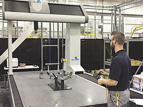
Introduced in 1959, coordinate measuring machines have become increasingly common over the last 2 decades. The complexity and cost once meant CMMs were only suitable for large manufacturers. Advances in CMM technology and manufacturing techniques have reduced the cost of ownership, and the machines are now found at all types and sizes of shops.
In operation, a CMM collects a series of 3D points by touching workpiece surfaces with a probe. Collection is done predominately through tactile scanning or touch-trigger operation, but some CMMs gather points through noncontact methods, such as laser scanning.

Courtesy of C. Tate
Joel Johnson, continuous improvement engineer for Mitsubishi Hitachi Power Systems Americas, sets up a CMM.
Touch-trigger operation is the more traditional and familiar technique. This method positions the probe above a part and, through a known vector, moves the probe until it contacts the surface. When contact is made, the probe is triggered and the CMM saves the coordinates of the touched point.
Tactile scanning places the probe in contact with the surface and follows a programmed path while maintaining a constant force against the surface. As the probe is driven along the path, a series of points is gathered and stored.
Determining the best measurement method depends mostly on the part configuration and the analysis that needs to be performed. In general, the scanning probe is a better choice when measuring features for flatness, roundness, profile and similar forms because it quickly gathers large numbers of data points. More data points give greater detail, making analysis easier. Touch-trigger probing can gather the same number of points and is as accurate, but takes longer.
After the points are collected, algorithms compare the condition of the surface to a programmed nominal value. Deviations from the nominal surface are compared to the allowable tolerance, and a report tells the operator which dimensions are acceptable and which are not.
A CMM can be more desirable than measuring with manual instruments such as micrometers, calipers and height gages because the CMM automates the process. Automating part measurement with a CMM can reduce the need for skilled personnel in the same way a CNC machine tool can. It is common for experienced personnel to program and set up CMMs and then have others operate them.
Although a CMM does not require an operator, systems robust enough to operate completely unmanned are rare. Inspection and adjustment often require human analysis.
CMMs can be integrated into automated manufacturing cells, where the CMMS are often loaded by robots. Once part data has been collected, CMMs can provide feedback to machine tools, whose coordinate systems and offsets are adjusted to maintain dimensions.
Flexibility is another common reason for buying a CMM. Hard gages, as the name implies, are rigid and built for one part or family of parts—often for measuring just one feature. If the part or process changes, hard gages must be reworked. CMMs, on the other hand, require only a revision in the CMM program.
Nonetheless, CMMs have drawbacks. They can be expensive and often require enclosures to provide a clean, temperature-controlled environment. Although mobile models “hardened” for use on the shop floor are available, CMMs are usually fixed in position, making them less flexible.
CMMs and the machine tools making the parts must work in unison. However, it is common for the machine tool programmer and the CMM programmer to disagree about part dimensions. Usually, the divergence is because the datum structure provided on the part drawing differs from that used in the manufacturing process.
For example, I worked at an aerospace company where the CMM reported the true position for a set of bolt holes to be out of tolerance. Operators corrected the problem by changing the hole coordinates in the CNC program. In the end, it was discovered that the CMM inspection fixture did not properly locate the datum used to calculate true position. The datum and the holes were machined in the same setup, which means there is little chance the true position could be out of tolerance. If the CMM and machine tool programmers had worked together, this situation probably would not have occurred. CTE

About the Author
Christopher Tate is engineering manager, combustion shop, for Mitsubishi Hitachi Power Systems Americas, Savannah (Ga.) Machinery Works. Email: [email protected].
Related Glossary Terms
- computer numerical control ( CNC)
computer numerical control ( CNC)
Microprocessor-based controller dedicated to a machine tool that permits the creation or modification of parts. Programmed numerical control activates the machine’s servos and spindle drives and controls the various machining operations. See DNC, direct numerical control; NC, numerical control.
- fixture
fixture
Device, often made in-house, that holds a specific workpiece. See jig; modular fixturing.
- tolerance
tolerance
Minimum and maximum amount a workpiece dimension is allowed to vary from a set standard and still be acceptable.


