Every shop, large or small, is constantly trying to improve productivity and part quality. The drive to reduce setup times and operator intervention has led to the proliferation of multitask machines.
Multitask machines range in price and complexity from lathes capable of driving rotating tools to large machining centers that can effectively perform the turning and milling operations needed to complete complex parts in one setup.
It is easy to understand how multitask machines can improve productivity, but the complexity that makes them more productive requires machinists and engineers to reconsider how they approach machining operations. Successful implementation of a multitask machine requires careful planning and consideration of key elements.
Multitask machines can have complex and expensive features, such as large tool magazines, probes, tool measurement systems and monitoring devices. These features allow users to maximize gains from the machine by limiting human interaction.
However, setup and learning to use these tools can be challenging. Shops should carefully consider training requirements needed to properly operate and program multitask machines. Gaining the maximum benefit requires efficient utilization of the features, and it is easy to overlook training. Training is rarely given on-site, which means employees must travel for training. Travel is expensive and negatively impacts shop production, making it likelier a shop will circumvent the training process. Insufficient training will result in less-than-efficient use of a machine and could lead to serious damage from misuse.
CAM software is required to efficiently program these machines. Proper utilization of CAM software requires training, which, like machine training, can be expensive and disrupt production.

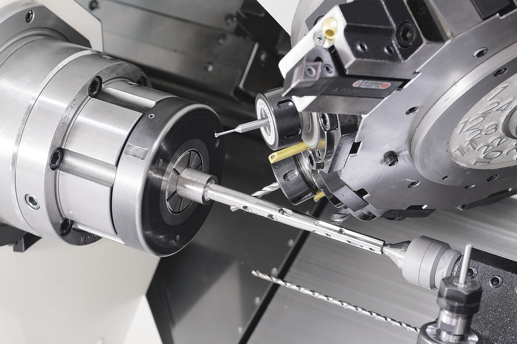
Multitask machines, such as this Nakamura-Tome NTJ 100 with a B-axis upper turret for machining features at any angle, are going to continue to grow in popularity as manufacturers push to increase productivity. Image courtesy Methods Machine Tools.
In addition, a significant amount of development time often is needed to get the post-processor for the CAM software to where it will provide the desired CNC code for the machine control. As machine complexity increases, so does the time needed to develop the post-processor. Development time can delay the return on investment while causing quality and delivery issues.
Verification software to accompany the CAM software is another consideration. When the machines are large, the parts are expensive or there are a large number of simultaneous operations, the risk of making a serious programming mistake rises. In these cases, verification software is needed to ensure the programs are proven out in the virtual world so that risk to the part and machine is minimized.
Verification software uses 3D models of the machines, fixtures and parts to simulate machining operations and highlight possible programming issues before the parts and program arrive at the machine. Many shops will not invest in verification software, deciding instead to rely solely on the simulation feature in the CAM software—a risky proposition. Without verification software, someone must carefully step through the program and look for and correct errors, which can be time-consuming. Minimizing development time for a new job is critical, and verification software allows much of the development to be done before a part goes to the machine.
Costs associated with verification software must also be considered. Like CAM software, verification software is an additional expense and requires training. It also requires a substantial amount of development time to create models of the machines, fixtures and cutting tools.
The machine-selection process should include planning each job intended for a machine to ensure the machine has enough and capability to run the job. At Mitsubishi, we have a multiple-axis lathe with live tools on the turret. When we put the first job on the machine, we found that the turret was incapable of 3-axis motion, which was disruptive to the development schedule as we had to completely rethink the machining operations. A little planning and some discussions with the machine tool builder’s application engineer would have helped us be more successful.
Planning for jobs should also include studying the time required to set up cutting tools in the machine. Reducing the number of setups and setup times is one of the prime motivators for investing in these machines.
Multitask machines are going to continue to grow in popularity as manufacturers push to increase productivity. However, if you’re in the market to buy such a machine, you need to plan carefully and conduct extensive research. You should discuss the machine’s capabilities in great detail with the builder to ensure it meets your needs.
Also, talk to the builder’s customers to get their input on the machine’s capabilities, and ask them to share any advice they can offer about multitask machining. You might be able to learn from their mistakes.
About the Author: Christopher Tate is operations manager, combustion shop, for Mitsubishi Hitachi Power Systems Americas, Savannah (Ga.) Machinery Works. Email: [email protected].
Related Glossary Terms
- centers
centers
Cone-shaped pins that support a workpiece by one or two ends during machining. The centers fit into holes drilled in the workpiece ends. Centers that turn with the workpiece are called “live” centers; those that do not are called “dead” centers.
- computer numerical control ( CNC)
computer numerical control ( CNC)
Microprocessor-based controller dedicated to a machine tool that permits the creation or modification of parts. Programmed numerical control activates the machine’s servos and spindle drives and controls the various machining operations. See DNC, direct numerical control; NC, numerical control.
- computer-aided manufacturing ( CAM)
computer-aided manufacturing ( CAM)
Use of computers to control machining and manufacturing processes.
- gang cutting ( milling)
gang cutting ( milling)
Machining with several cutters mounted on a single arbor, generally for simultaneous cutting.
- lathe
lathe
Turning machine capable of sawing, milling, grinding, gear-cutting, drilling, reaming, boring, threading, facing, chamfering, grooving, knurling, spinning, parting, necking, taper-cutting, and cam- and eccentric-cutting, as well as step- and straight-turning. Comes in a variety of forms, ranging from manual to semiautomatic to fully automatic, with major types being engine lathes, turning and contouring lathes, turret lathes and numerical-control lathes. The engine lathe consists of a headstock and spindle, tailstock, bed, carriage (complete with apron) and cross slides. Features include gear- (speed) and feed-selector levers, toolpost, compound rest, lead screw and reversing lead screw, threading dial and rapid-traverse lever. Special lathe types include through-the-spindle, camshaft and crankshaft, brake drum and rotor, spinning and gun-barrel machines. Toolroom and bench lathes are used for precision work; the former for tool-and-die work and similar tasks, the latter for small workpieces (instruments, watches), normally without a power feed. Models are typically designated according to their “swing,” or the largest-diameter workpiece that can be rotated; bed length, or the distance between centers; and horsepower generated. See turning machine.
- milling
milling
Machining operation in which metal or other material is removed by applying power to a rotating cutter. In vertical milling, the cutting tool is mounted vertically on the spindle. In horizontal milling, the cutting tool is mounted horizontally, either directly on the spindle or on an arbor. Horizontal milling is further broken down into conventional milling, where the cutter rotates opposite the direction of feed, or “up” into the workpiece; and climb milling, where the cutter rotates in the direction of feed, or “down” into the workpiece. Milling operations include plane or surface milling, endmilling, facemilling, angle milling, form milling and profiling.
- turning
turning
Workpiece is held in a chuck, mounted on a face plate or secured between centers and rotated while a cutting tool, normally a single-point tool, is fed into it along its periphery or across its end or face. Takes the form of straight turning (cutting along the periphery of the workpiece); taper turning (creating a taper); step turning (turning different-size diameters on the same work); chamfering (beveling an edge or shoulder); facing (cutting on an end); turning threads (usually external but can be internal); roughing (high-volume metal removal); and finishing (final light cuts). Performed on lathes, turning centers, chucking machines, automatic screw machines and similar machines.
Author

Christopher Tate is the owner of Tate Engineering, a Natchez, Mississippi, firm that helps manufacturers solve efficiency problems. Tate, who earned master's degree in industrial technology from Mississippi State University, has 32 years of experience in the metalworking industry.


