Exploring the ins and outs of specifying and ordering a flexible specialty machine tool and having a machine builder produce it.
Standard machine tools are well suited for job shops, which typically don’t know the type of work that’s coming next. But OEMs often need specialty machine tools for mission-critical applications that can run for years—and flexibility is one of the key features sought by manufacturers that use specialty machine tools.
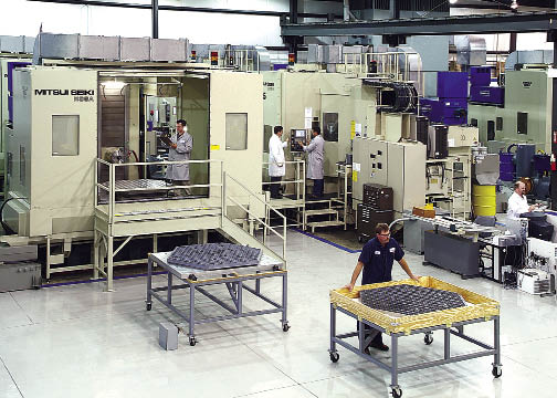
Courtesy of Mitsui Seiki
The James Webb Space Telescope machining department at Axsys Technologies.
This article focuses on the best ways to plan for, order and implement a specialty machine tool. Some of the guidelines builders and end users recommend include:
• Starting with a geometrical specification for the machine;
• Preparing a list of required components by brand name; and
• Devoting an individual to act as the go-to person when issues arise.
During the build process, end users should expect:
• To receive regular updates about the process even if everything is progressing smoothly;
• To have all impacted personnel meet with the builder when discussing possible design changes; and
• To provide feedback about how to build flexibility into a specialty machine.
For example, flexibility is one critical requirement for a machine Bertsche Engineering Corp. is currently building. The Buffalo Grove, Ill., company builds custom machines, primarily for the aerospace industry, as well as standard metalcutting and high-pressure water and mechanical deburring machines. According to Richard Bertsche, company president, the customer wanted a lot of flexibility to machine various small to large workpieces on the same machine.
Bertsche designed the machine, which can be run as a single or dual work cell, with six 40 "×20 "×20 " work cubes. “They will have a machine in excess of 240 ",” he said. “When they run it as a single work cell, they’ll have big worktables in there. They will be reconfiguring the worktables daily.”
That will allow the parts manufacturer to support its other production requirements by having one machine that can morph into the machine that’s needed. Bertsche Engineering enabled that by customizing a standard machine with reconfigurable worktables and “sophisticated” workholding devices. “We designed that functionality into the machine, and we really had to wait for a customer with a work environment and a machining need that required that functionality,” Bertsche said.
Based on Rock—not Metal
Flexibility was also a central part of the custom, 2-axis internal grinding machine CNC North Inc. built for a Canadian manufacturer of aerospace landing gear. CNC North designed the grinder so the workhead and steady rest move together on a rail so the operator can set them where he wants. “We provided him all the flexibility in the world for moving his workhead and steady rest in and out,” said Patrick Harrington, company president. Although landing gear components are the customer’s primary focus, Harrington added that “he wanted flexibility to be able to bid and process additional parts.”
Courtesy of Bertsche Engineering
A custom metalcutting machine tool from Bertsche Engineering.
Incorporated in 2005, the Springfield, Vt., company initially focused on supporting, remanufacturing and providing design enhancements for Bryant Grinder CNC machines, in part because CNC North’s mechanical engineers are all former Bryant engineers. However, the company expanded its capabilities last year from machine remanufacturing to building new grinders and the 2-axis internal grinder is its first. “We are now quoting more new and specialty machines than we are rebuilding,” Harrington noted.
The new CNC machine replaced a hydraulic, manually operated grinder, but it had to fit the exact footprint of the old one because of limited floor space. That gave CNC North an advantage over other builders offering competitive bids but for already-designed grinders that, in most cases, were too large. “We were very competitive on price and lead time by doing it with a custom application,” Harrington said.
Instead of designing a pattern for a cast iron bed and then having a foundry produce the special casting, CNC worked with Rock of Ages, Barre, Vt., to create a solid-granite base. “It was African black—the densest granite you can purchase,” Harrington said. That provided a cost-effective solution for designing a bed to accept the specific hydrostatic slides, workheads, fixtures and other components that the machine was configured for. In addition, a casting should be aged prior to utilizing it, “where the granite has been aged for years and years and years,” Harrington said.
CNC North provided custom guarding to meet Canadian regulations. After developing a 3-D model of the initial guarding design with two doors, CNC North went to the customer’s facility and met with the operators and safety and setup personnel to gather their input. “We did a bunch of what-ifs,” Harrington said. “If you have to get access to the dresser, where do you need access to it? If you need to adjust the steady rest, where do you need access?”
As a result, CNC North reconfigured the guarding to have three doors, making setup easier.
Tightest Tolerances
An end user also requires a specialty machine tool when the specified tolerances are tighter than what standard offerings can achieve, such as the one machine builder Mitsui Seiki (USA) Inc., Franklin Lakes, N.J., delivered to Axsys Technologies Inc., Rocky Hill, Conn., for producing the beryllium lenses for NASA’s James Webb Space Telescope. According to NASA, the JWST will be the most sensitive infrared space telescope ever built, and its mission includes peering into the universe’s farthest galaxies to see the first stars.
That required a machine tool that’s been hand scraped and manually fitted and built in a temperature-controlled environment to ±0.2° C from floor to ceiling on a 1,200mm concrete foundation to eliminate vibration, according to Scott Walker, Mitsui Seiki president. “We assemble the machine, measure it, take it apart, make a correction, reassemble it, take it apart again if necessary and continue to do so until the machine comes into the tolerance that’s been sold,” Walker said. If the part is quite heavy, say 8 tons, scraping accuracy for the X-axis, for example, needs to be measured with the weight on it so the travel is straight with the weight in place, and the axis will not be straight without the weight.
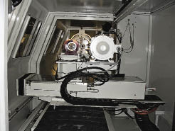
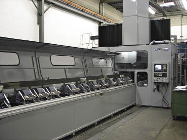
Courtesy of CNC North
The steady rest slide in a specialty 2-axis grinder from CNC North.
The process begins with a geometrical specification for the machine. “We picked 25 identifiable, measurable procedures and argued about each one,” Walker said. Then, before the contract is released, Mitsui Seiki guarantees what the resulting measurement will be in its factory environment when measured in a specified manner.
Kyle Klamar, vice president of engineering for Allis Tool & Machine Corp., noted that after meeting with a customer to identify production bottlenecks or other challenges to overcome, he develops a conceptual design to solve the problem. He then obtains a list of specific components a customer requires, such as a conveyor from a certain manufacturer. Starting with those constraints, a formal design is developed around them. “First and foremost, we always identify that criteria before we move forward because we can be headed down a path that our customers are not interested in or not willing to accept,” he said. Other times, price is the only constraint. “They’ll say ‘come up with a quote for us that’s the most cost-effective as you can using any components you select.’ ”
Allis Tool & Machine builds custom equipment such as thermal curing chambers, automated part loaders/unloaders, assembly machines and drilling and tapping machines. The Milwaukee-based company also does low-volume prototype and production machining of medium to large parts, as well as machining of the components needed for its specialty machines, such as bases, fixture plates and risers.
According to Bertsche, custom machines are almost always sold to a customer-generated specification that is initially generic. “Typically, it starts out that the customer has a problem and he’s looking for a machining solution,” he said. “The first set of specifications oftentimes just describes what the customer needs to have.”
The end user is often looking for a concept that allows him to better define his requirements before a specification is created that then goes out for bid, Bertsche noted. The specification gets refined based on feedback from builders before being submitted for final bidding. The winning bidder then develops a working system based on the proposed concept. “Once you’ve been awarded an order, there’s a number of design reviews required,” Bertsche said. “As you get to some of those decision points, certain elements have to be jointly decided between the customer and builder.”
For larger companies, such as a Fortune 500 OEM, one area in the design process that isn’t jointly decided is certain critical purchased components. Those are quoted to a plant standard or specification, usually from a maintenance perspective, so an adequate supply of spare parts is available in inventory, Bertsche noted.
Customer Relations
Although the machines Allis Tool builds vary, one constant is the need to provide customers with updates throughout the building process. “Whenever we’re building something we’re constantly in contact with the customer,” Klamar said, adding that customers are contacted both when there’s a hiccup in the project and when it’s smooth sailing. “Communication throughout the entire process is essential.”
Walker noted that every end user/builder relationship involves give-and-take, and the machine for the telescope project was no exception. The machine’s Y-axis travel straightness had to be extremely accurate because the lenses were 1.5m in diameter and have machined features on the top and bottom, and pallet wobble had to be kept to an absolute minimum because the front and back faces of each lens required machining. “And they let go of some of the tolerance criteria in the X-axis and Z-axis to accomplish that,” Walker said.
Mitsui Seiki sold eight machines for the JWST project and 18 lenses were required to make the telescope’s aperture. Each workpiece weighs about 700 lbs. and ends up as a 25-lb. lens after 6,600 hours of machining time. “Typically, these kinds of machines are designed for 75,000 hours of operational use,” Walker said, “and 75,000 hours is three shifts a day, 7 days a week for 12 years. That’s your straight depreciation schedule so you can fully depreciate the machine over the life of its application.”
That means after producing the lenses, plenty of machine life remained. “They’re making other types of components but the customer who purchased them is still using the machines,” Walker noted, meaning even application-specific specials offer flexibility.
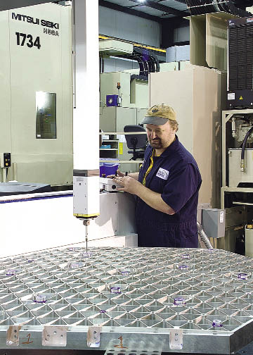
Courtesy of Mitsui Seiki
A coordinate measuring machine is on Axsys Technologies’ shop floor to check the mirrors for the James Webb Space Telescope during and after processing.
When an OEM requires ultraprecise application-specific machines for producing its core-competency products, the machine builder is bound by proprietary agreements to not release any information or provide similar designs to other customers. In return, the OEM gives the builder access to its R&D, engineering and product design personnel. That can be beneficial when developing a production-ready solution for a machining challenge, such as providing a specific spindle stiffness characteristic from one machine to another. “That’s very tough to do,” Walker said, “and I don’t have the R&D resources in my company to put a couple Ph.D.s on it and figure out how to do it. OEMs do and if they can work with our design people and come up with some way to measure it, then we can meet the objective.”
Even when a standard machine is customized to satisfy a specific project or application (see sidebar on page 52), communication between the dealer and customer is essential. That was the case when Schultes Precision Manufacturing, Buffalo Grove, Ill., purchased a Kitamura horizontal machining center from Machine Tool Technology-21 Inc., Schaumburg, Ill. “There was updating of the progress so I knew where they stood and they knew where I stood,” said Alex Patent, manufacturing manager for Schultes Precision Manufacturing. “It went very smooth.”
Both parties might dedicate an engineer to provide technical assistance to each other during the customization process, which Klein Tools Inc., Skokie, Ill., did when it also purchased a specialty Kitamura machine from MTT-21. “The lines of communication were always open and there was always a go-to person available so any questions that came up from either us or from them were cleared up rather quickly,” said Mike Baker, manufacturing manager for Klein Tools. “We also did our homework as far as documenting specifically what the expectations were for both parties on this project, so after the order was placed there were no gray areas.”
While specifications vary, flexibility seems assured to be a fundamental requirement of customized and specialty machine tools. “We see a need for equipment that is not specially designed for one part or product only,” said Mark T. Ulanov, president of MTT-21. “This equipment needs to be flexible to give our customers the ability to produce a variety of different parts with short cycle times, minimum labor involvement and reduced setup times.” CTE
About the Author: Alan Richter is editor of Cutting Tool Engineering, having joined the publication in 2000. Contact him at (847) 714-0175 or [email protected].
Courtesy of All images: A. Richter
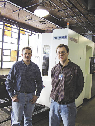
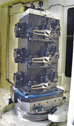
Klein Tools’ Manufacturing Manager Mike Baker (top left) and Production Engineer Christopher R. Babel in front of the industrial hand tool manufacturer’s Kitamura Mycenter-HX400iF HMC that features special hydraulically operated multistation fixtures (bottom).
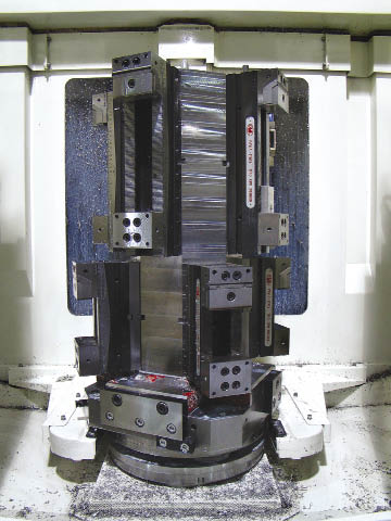
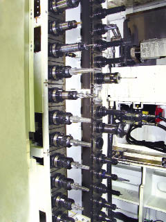
MTT-21 designed special fixtures for Schultes’ Kitamura Mycenter-HX400iF HMC (top) to provide appropriate spacing between the manually operated vises and enable adequate clearances for the array of tools applied (bottom).
Customizing machines to compete in a down market
From 1989, Machine Tool Technology-21 Inc., Schaumburg, Ill., has sold Kitamura stand-alone machine tools. During the past 5 to 10 years, MTT-21 has seen a trend toward providing customers with not only the machines but also optional accessories, fixturing and tooling to reduce cycle times and increase productivity. This enables end users to machine new parts more efficiently with less or no labor.
A case in point is the Kitamura Mycenter-HX400iF horizontal machining center with a two-position automatic pallet changer that MTT-21 customized for Klein Tools Inc., Skokie, Ill. The manufacturer of industrial hand tools found the machining process to be time consuming and labor intensive and turned to MTT-21 to find a way to reduce cycle times, minimize labor, improve equipment efficiency and extend tool life. To enable that, MTT-21 equipped the machine with:
• Special hydraulically operated multiple-station fixtures;
• A hydraulic power unit to activate the fixtures;
• A spindle probe for registering the locations of the carbon steel forgings to be machined;
• A laser-based tool breakage detection system for tool setting and monitoring;
• A high-pressure coolant-through-the-spindle system; and
• A Royal programmable mist collector to prevent the mist generated when drilling from obstructing the laser detector.
According to Mike Baker of Klein Tools Inc., there were two main aspects to the project. “We were looking for a machine that was very robust and could handle severe cuts and would make a lot parts really fast,” he said. “The other aspect was fixturing that allows us to put more parts on the machine than our older fixtures.”
The new fixtures enabled Klein to machine six matched sets of parts vs. four matched sets previously. The parts are for wire pulling tools called Chicago Grips.
The hydraulic fixtures also provided an ergonomic advantage for the operators who previously used an impact-type screw gun that vibrated to clamp parts onto a fixture. The new fixtures are also more efficient. “The hydraulic fixtures free up operator time to manage the other machines in the cell where before there were issues with machines waiting for the operator because he got behind in his loading,” Baker said. “Now it’s just one flip of the valve and he’s ready to go.”
In addition to speeding up the workholding process, cycle times are quicker on the new machine. Christopher R. Babel, production engineer for Klein Tools, noted that, compared to the previous machine, the Kitamura increased the average cutting speed from 5 ipm to 30 ipm when drilling and from 8 ipm to 30 ipm when milling, with milling being the primary operation.
Machining the parts requires many specialty cutting tools and the tools are lasting significantly longer on the new machine, which is faster and more rigid than the machining technology from the late ’80s that Klein was using. Because Klein has only been operating the Kitamura for about six weeks, the manufacturer hasn’t been able to quantify any tool life increase, but knows it’s significant. “There are drills in the machine we haven’t even changed yet,” Baker said. “On our old machine, we would have changed them multiple times by now.”
The total length of the project from receipt of the purchase order until the equipment was accepted at Klein’s facility was 7 months. “MTT-21 met the delivery requirements,” Baker said. “It was really a smooth project.”
Delivering a customized machine to Schultes Precision Manufacturing presented a different challenge. The job shop needed a machining process where twice as many 6061 aluminum hydraulic manifolds could be loaded onto a pallet than previously without going to a large machine—and it was needed fast. “We needed the machine in 8 weeks because we had to deliver parts to a customer,” said Alex Patent of Schultes Precision Manufacturing, Buffalo Grove, Ill.
MTT-21 provided a quote in about a week for a Kitamura Mycenter-HX400iF HMC rather than a bigger machine, such as a Mycenter-HX630i, which costs more and has a CAT 50 spindle taper instead, whereas the smaller machine accepts CAT 40 toolholders. That meant Schultes wouldn’t have to purchase new toolholders. “When MTT-21 said they can do it on an HX400iF, I was like OK, I don’t know how they’re going to do it but I’ll be happy to see it,” Patent said.
“We designed and manufactured special fixturing to accommodate more parts on the pallet without creating any interferences and preserving the ability to machine three sides on every part on the pallet,” said Mark T. Ulanov of MTT-21. The workpieces are held with vises on a pallet-mounted tombstone, and Schultes is able to complete four workpieces per pallet, or eight pieces per cycle.
In addition, MTT-21 equipped the machine with a Renishaw spindle probe for registering workpiece location, a Renishaw laser-based tool breakage detection system for tool monitoring and a 1,000-psi coolant-through-the-spindle system to provide adequate chip evacuation, especially when applying long port tools. Because parts are loaded by hand and their locations can vary, for example by 0.050 ", the machine probes each part and sends offsets to the control. “The machine now knows exactly where the part is located,” Patent said.
When the machine was scheduled for delivery, Patent said it arrived already setup and joined the shop’s 14 other Kitamura machines.
—A. Richter
Contributors
Allis Tool & Machine Corp.
(414) 453-5500
www.allistool.com
Bertsche Engineering Corp.
(847) 537-8757
www.bertsche.com
CNC North Inc.
(802) 885-6675
www.cnc1.com
Klein Tools Inc.
(800) 553-4676
www.kleintools.com
Machine Tool Technology-21 Inc.
(847) 891-1000
www.mtt21.com
Mitsui Seiki (USA) Inc.
(201) 337-1300
www.mitsuiseiki.com
Schultes Precision Manufacturing
(847) 465-0300
www.schultes.com
Related Glossary Terms
- 3-D
3-D
Way of displaying real-world objects in a natural way by showing depth, height and width. This system uses the X, Y and Z axes.
- computer numerical control ( CNC)
computer numerical control ( CNC)
Microprocessor-based controller dedicated to a machine tool that permits the creation or modification of parts. Programmed numerical control activates the machine’s servos and spindle drives and controls the various machining operations. See DNC, direct numerical control; NC, numerical control.
- cutting speed
cutting speed
Tangential velocity on the surface of the tool or workpiece at the cutting interface. The formula for cutting speed (sfm) is tool diameter 5 0.26 5 spindle speed (rpm). The formula for feed per tooth (fpt) is table feed (ipm)/number of flutes/spindle speed (rpm). The formula for spindle speed (rpm) is cutting speed (sfm) 5 3.82/tool diameter. The formula for table feed (ipm) is feed per tooth (ftp) 5 number of tool flutes 5 spindle speed (rpm).
- fixture
fixture
Device, often made in-house, that holds a specific workpiece. See jig; modular fixturing.
- gang cutting ( milling)
gang cutting ( milling)
Machining with several cutters mounted on a single arbor, generally for simultaneous cutting.
- grinding
grinding
Machining operation in which material is removed from the workpiece by a powered abrasive wheel, stone, belt, paste, sheet, compound, slurry, etc. Takes various forms: surface grinding (creates flat and/or squared surfaces); cylindrical grinding (for external cylindrical and tapered shapes, fillets, undercuts, etc.); centerless grinding; chamfering; thread and form grinding; tool and cutter grinding; offhand grinding; lapping and polishing (grinding with extremely fine grits to create ultrasmooth surfaces); honing; and disc grinding.
- grinding machine
grinding machine
Powers a grinding wheel or other abrasive tool for the purpose of removing metal and finishing workpieces to close tolerances. Provides smooth, square, parallel and accurate workpiece surfaces. When ultrasmooth surfaces and finishes on the order of microns are required, lapping and honing machines (precision grinders that run abrasives with extremely fine, uniform grits) are used. In its “finishing” role, the grinder is perhaps the most widely used machine tool. Various styles are available: bench and pedestal grinders for sharpening lathe bits and drills; surface grinders for producing square, parallel, smooth and accurate parts; cylindrical and centerless grinders; center-hole grinders; form grinders; facemill and endmill grinders; gear-cutting grinders; jig grinders; abrasive belt (backstand, swing-frame, belt-roll) grinders; tool and cutter grinders for sharpening and resharpening cutting tools; carbide grinders; hand-held die grinders; and abrasive cutoff saws.
- inches per minute ( ipm)
inches per minute ( ipm)
Value that refers to how far the workpiece or cutter advances linearly in 1 minute, defined as: ipm = ipt 5 number of effective teeth 5 rpm. Also known as the table feed or machine feed.
- machining center
machining center
CNC machine tool capable of drilling, reaming, tapping, milling and boring. Normally comes with an automatic toolchanger. See automatic toolchanger.
- metalcutting ( material cutting)
metalcutting ( material cutting)
Any machining process used to part metal or other material or give a workpiece a new configuration. Conventionally applies to machining operations in which a cutting tool mechanically removes material in the form of chips; applies to any process in which metal or material is removed to create new shapes. See metalforming.
- milling
milling
Machining operation in which metal or other material is removed by applying power to a rotating cutter. In vertical milling, the cutting tool is mounted vertically on the spindle. In horizontal milling, the cutting tool is mounted horizontally, either directly on the spindle or on an arbor. Horizontal milling is further broken down into conventional milling, where the cutter rotates opposite the direction of feed, or “up” into the workpiece; and climb milling, where the cutter rotates in the direction of feed, or “down” into the workpiece. Milling operations include plane or surface milling, endmilling, facemilling, angle milling, form milling and profiling.
- steady rest
steady rest
Supports long, thin or flexible work being turned on a lathe. Mounts on the bed’s ways and, unlike a follower rest, remains at the point where mounted. See follower rest.
- stiffness
stiffness
1. Ability of a material or part to resist elastic deflection. 2. The rate of stress with respect to strain; the greater the stress required to produce a given strain, the stiffer the material is said to be. See dynamic stiffness; static stiffness.
- tapping
tapping
Machining operation in which a tap, with teeth on its periphery, cuts internal threads in a predrilled hole having a smaller diameter than the tap diameter. Threads are formed by a combined rotary and axial-relative motion between tap and workpiece. See tap.
- tolerance
tolerance
Minimum and maximum amount a workpiece dimension is allowed to vary from a set standard and still be acceptable.
Author

Alan holds a bachelor’s degree in journalism from Southern Illinois University Carbondale. Including his 20 years at CTE, Alan has more than 30 years of trade journalism experience.


