Paul Schurman Machine Inc., Ridgefield, Wash., started in the 1950s by providing machining services to farmers, loggers and other customers with large parts and equipment. Over a half century later, the shop has reinvented itself in response to changes in markets and industrial technology while still maintaining a focus on efficient machining of large components. For example, the shop has seen its business of modifying and repairing large components for wind-power generators grow.
A recent example is the shop’s rebuild of a 5-ton bearing assembly that supports a shaft driven by two 10,000-hp electric motors at a steel rolling mill.
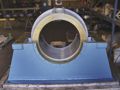
Courtesy of Paul Schurman Machine
In this 5-ton bearing assembly rebuilt by Paul Schurman Machine, removing the top half of outer housing reveals a cast-steel bearing carrier and the thin Babbitt bearing it contains.
The heart of the assembly was a 26 "-ID, 22 "-deep × ¼ "-thick plain Babbitt bearing mounted in a 39½ "-dia., two-piece cast steel bearing carrier. The carrier’s OD had a spherical contour machined to match an identical shape inside the bearing’s massive steel outer housing. The spherical mating surfaces enabled the bearing carrier to move back and forth and from side to side inside the housing. In use, the bearing and housing are filled with oil and “when it’s running, everything floats on a film of high-pressure oil,” said Project Manager Scott Beaudoin.
A complete inspection of the assembly as received from the customer revealed galling, fettering and out-of-round conditions among the bearing components. General Manager Matt Houghton determined it would be necessary to “take out the Babbitt bearing and repour and remachine it, do cleanup on the OD of the bearing carrier, then weld up the ID of the outer housing and remachine the factory clearances to fit the carrier.”
Babbitt bearings came into use in the mid-19th century. The Babbitt alloy usually contains lead, tin, zinc or copper. The base metal is soft and easily damaged, but the alloy contains hard crystals that are exposed as the softer metal wears. The crystals become the bearing surface while the worn areas between them hold and convey lubricant.
Houghton acknowledged that while Babbitt bearings are old-fashioned, they are still used in many industrial applications. A bearing of this size usually has to be repaired instead of replaced because finding or manufacturing a new plain bearing would be too expensive and time-consuming.
Schurman removed the old bearing from the carrier and fabricated the molds, pouring apparatus and fixturing to cast a new one. “For the mold, you have to have pieces you can mechanically take apart to get it off the Babbitt,” Beaudoin said. “We rolled steel, then bolted it together,” noting that the mold comprised eight separate parts. The carrier consisted of two bolt-together semicircular segments, and the shop molded half the bearing separately in each segment. Each half bearing required 5 gal. of Babbitt—a big pour.
Because Babbitt shrinks as it cools, the mold was engineered to leave 3⁄8 " of extra stock on the bearing ID and 6 "-long risers of excess alloy on each end of the bearing. “You have the Babbitt hanging out past the steel,” Houghton said. “Then you have to machine it off to the base metal on each half of the carrier so you have two halves that you can bolt together.”
Schurman milled the excess Babbitt on a 5-axis CNC Femco horizontal boring machine using a 4 "-dia. facemill tooled with carbide inserts. The cutter ran at 1,200 rpm and a feed rate of 50 ipm, with a final pass at 25 ipm to enhance the surface finish.
The carrier halves were then bolted together and the round bearing/carrier unit was put on a vertical boring machine for milling to square the bearing faces relative to the bore.
Next, the carrier was moved back to the HBM to machine the spherical contour on its OD. “We had to cleanup the outside of the inner section before we knew what we should bore on the ID of the housing,” Houghton said. Cleanup of the spherical contour on the carrier OD involved removal of 0.030 " of material. The machine table turned 360° at about 20 ipm. A 1 " inscribed-circle button cutter, running at 2,500 rpm, machined the contour as the machine spindle moved in the X, Y and Z axes. Machining the bearing carrier’s spherical OD consumed 2½ days of continuous, lights-out operation. “To get a good finish with the button cutter, step-over was only about 0.020 ",” Beaudoin said.
The dimensions of the newly machined carrier OD determined the parameters for machining the main housing’s ID, with the goal of re-establishing the original clearances of 0.011 " to 0.015 ". The shop cut the housing ID’s spherical radius on the HBM with a custom tool fitted with round inserts. Machining time consumed 40 hours.
Up to this point, the Babbitt bearing surface had remained in its as-cast condition. “We left it that way because with all the handling of the part, it is really hard to keep from putting a ding in this soft material,” Beaudoin said. The shop then put the carrier on the VBM and rough bored the bearing ID to within 0.030 " per side of the final diameter. Then the two bearing halves were taken apart and put back on the HBM, where endmills and a slitting cutter machined slots, grooves and reliefs in the bearing face for clearance and oil flow.
Finally, the halves were reassembled and the carrier went back on the VBM for finish boring. Tolerance for the final bore was ±0.005 ". Beaudoin said the tolerance left some extra material on the bearing surface because the customer “didn’t know what condition their main drive shaft was going to be in. The extra material will permit the customer to hand scrape the bearing for final fit if necessary.” A day of setup and 8 hours of machining were required to finish the bearing ID.
“The key to producing a heavy part is getting it up on the machine and set up right,” Beaudoin said. “Most of the time, that’s the complicated part of the job—not the actual machining.”
Paul Schurman Machine is getting ready to handle even bigger parts. Within the last year, the shop acquired and rebuilt an Ingersoll Machine Tools planer mill with a 36 '-long × 101 "-wide table and 56 " capacity in the Z-axis. Working with local integrator Applied Motion Systems Inc., Vancouver, Wash., the shop customized a 3-axis CNC, and the former single-point machine now features three heads and 3-axis capability. Paul Schurman Machine is fielding inquiries from potential customers in the pump and valve, wind power and heavy construction industries. CTE
For more information about Paul Schurman Machine Inc. call (360) 887-3193 or visit www.schurmanmfg.com.
Related Glossary Terms
- boring
boring
Enlarging a hole that already has been drilled or cored. Generally, it is an operation of truing the previously drilled hole with a single-point, lathe-type tool. Boring is essentially internal turning, in that usually a single-point cutting tool forms the internal shape. Some tools are available with two cutting edges to balance cutting forces.
- boring machine
boring machine
Similar to a turning machine except that the cutting tool (single-point or multiple-cutting-edge), rather than the workpiece, rotates to perform internal cuts. However, boring can be accomplished by holding the tool stationary and turning the workpiece. Takes a variety of vertical, slanted and horizontal forms, and has one or more spindles. Typically a large, powerful machine, it can readily hold tolerances to 0.0001". See jig boring; lathe; turning machine.
- button cutter
button cutter
Round insert that is able to spread the stresses generated by the cutting forces over a larger area than other insert shapes. However, a round insert generates higher axial forces, which transfer into the workpiece.
- clearance
clearance
Space provided behind a tool’s land or relief to prevent rubbing and subsequent premature deterioration of the tool. See land; relief.
- computer numerical control ( CNC)
computer numerical control ( CNC)
Microprocessor-based controller dedicated to a machine tool that permits the creation or modification of parts. Programmed numerical control activates the machine’s servos and spindle drives and controls the various machining operations. See DNC, direct numerical control; NC, numerical control.
- facemill
facemill
Milling cutter for cutting flat surfaces.
- feed
feed
Rate of change of position of the tool as a whole, relative to the workpiece while cutting.
- galling
galling
Condition whereby excessive friction between high spots results in localized welding with subsequent spalling and further roughening of the rubbing surface(s) of one or both of two mating parts.
- gang cutting ( milling)
gang cutting ( milling)
Machining with several cutters mounted on a single arbor, generally for simultaneous cutting.
- gang cutting ( milling)2
gang cutting ( milling)
Machining with several cutters mounted on a single arbor, generally for simultaneous cutting.
- inches per minute ( ipm)
inches per minute ( ipm)
Value that refers to how far the workpiece or cutter advances linearly in 1 minute, defined as: ipm = ipt 5 number of effective teeth 5 rpm. Also known as the table feed or machine feed.
- inner diameter ( ID)
inner diameter ( ID)
Dimension that defines the inside diameter of a cavity or hole. See OD, outer diameter.
- milling
milling
Machining operation in which metal or other material is removed by applying power to a rotating cutter. In vertical milling, the cutting tool is mounted vertically on the spindle. In horizontal milling, the cutting tool is mounted horizontally, either directly on the spindle or on an arbor. Horizontal milling is further broken down into conventional milling, where the cutter rotates opposite the direction of feed, or “up” into the workpiece; and climb milling, where the cutter rotates in the direction of feed, or “down” into the workpiece. Milling operations include plane or surface milling, endmilling, facemilling, angle milling, form milling and profiling.
- milling machine ( mill)
milling machine ( mill)
Runs endmills and arbor-mounted milling cutters. Features include a head with a spindle that drives the cutters; a column, knee and table that provide motion in the three Cartesian axes; and a base that supports the components and houses the cutting-fluid pump and reservoir. The work is mounted on the table and fed into the rotating cutter or endmill to accomplish the milling steps; vertical milling machines also feed endmills into the work by means of a spindle-mounted quill. Models range from small manual machines to big bed-type and duplex mills. All take one of three basic forms: vertical, horizontal or convertible horizontal/vertical. Vertical machines may be knee-type (the table is mounted on a knee that can be elevated) or bed-type (the table is securely supported and only moves horizontally). In general, horizontal machines are bigger and more powerful, while vertical machines are lighter but more versatile and easier to set up and operate.
- outer diameter ( OD)
outer diameter ( OD)
Dimension that defines the exterior diameter of a cylindrical or round part. See ID, inner diameter.
- planing machine ( planer)
planing machine ( planer)
Machines flat surfaces. Planers take a variety of forms: double-housing, open-side, convertible and adjustable open-side, double-cut and milling. Large multihead (milling, boring, drilling, etc.) planers and planer-type milling machines handle most planing work.
- step-over
step-over
Distance between the passes of the toolpath; the path spacing. The distance the tool will move horizontally when making the next pass. Too great of a step-over will cause difficulty machining because there will be too much pressure on the tool as it is trying to cut with too much of its surface area.
- titanium nitride ( TiN)
titanium nitride ( TiN)
Added to titanium-carbide tooling to permit machining of hard metals at high speeds. Also used as a tool coating. See coated tools.
- tolerance
tolerance
Minimum and maximum amount a workpiece dimension is allowed to vary from a set standard and still be acceptable.
Author
News items authored by Cutting Tool Engineering have been written or edited by the editors of Cutting Tool Engineering magazine. The reports represent material submitted to CTE by outside authors, and edited by CTE editors for style and accuracy.


