By Joe Pizzoferrato, Heidenhain applications engineer
Trochoidal milling has been around for quite some time. Many in the industry have seen direct positive impacts on tool longevity and higher removal rates (MRR) by utilizing its fundamentals. Conventional machining methods are out of date in many situations.
Due to the ongoing improvements in machine motion control, CAM systems, and the design of simple, easy-to-use Trochoidal Cycles available at many controls, it is worth looking into its practices for a long roughing routine or for tough, hard-to-machine materials.
Trochoidal milling has become a popular technique to utilize in slotting, pocketing, roughing, and machining of hard materials found in aerospace components such as titanium and Inconel where the chips are typically hard to break.
How does it work?

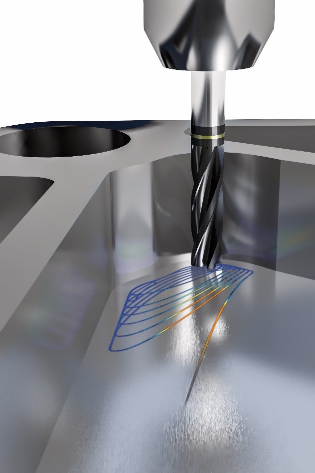
Imagine a satellite orbiting the earth at a constant height. If one were to apply a large enough force perpendicular to its orbital path to force it back to earth, it would exhibit a type of circular path. With each revolution, its rate of travel or pitch in this orbital path is its trochoidal movement. A circular motion with a low radial engagement and constant step-over (feed per tooth) is the best way to describe trochoidal motion.
Another similar type of toolpath motion that also reaps many of the benefits we will discuss is a peel-type toolpath. These toolpaths typically have an arc-in-path followed by a straight line or a line that follows the contour shape followed by an arc-out-path. There are specific parameters that generally describe a peel-type toolpath. Typically, it is around a maximum of 10% tool engagement with a maximum Z depth and higher feed rates between the transition moves. There is also a reduced feed rate upon entry to maintain the appropriate relationship in feed-per-tooth between the center of the cutter and the outside cutting edge upon engagement.
Capabilities and benefits of these strategies?
The advantages of low radial engagement in trochoidal milling create a reduced chip thickness that reduces the load on the tool, a positive byproduct of this strategy. A reduced deflection provides closer to nominal stock allowance in all areas of the contour. This helps to ensure the tool is removing the same amount of stock when finishing the surfaces, which will ensure uniform surface finish quality or integrity. Low radial engagement’s big advantage lowers the temperature at the cutting zone, which provides a less thermal load on the tool. This creates better predictability in a process and simultaneously provides better tool life.
Trochoidal milling techniques create superior chip removal, especially when M8 or air blast accompanies. Therefore, the possibility of having to re-cut chips is reduced. Uniform tool engagement both radially and axially is also a benefit of using these strategies. This translates to uniform wear along the cutting edges and also keeps the tool sharper longer due to the small radial engagement strategies created by the control or CAM system. Higher cutting parameters are also possible. This is because of chip thickness principles.
Chip thickness principles depend on the type of tool being used such as 90-, 45- or 10-degree cutting angle, and whether the user is peripheral or face milling. If performing periphery milling or side milling for a peel style operation with a standard flat endmill (90-degree edge), a factor or coefficient can be applied that will affect and increase the feed per tooth and thus maintain the same chip thickness as in a conventional machining process.
This factor depends on the relationship or ratio between ae (the working engagement) and (diameter of the cutter) D. This can result in anywhere between a 10-15% increase in MRR (metal removal rate) for that particular operation over conventional methods.
Lower cutting forces
With low radial engagement and utilizing as much of the flute length as possible, the machining operation will also generate lower cutting forces. This helps the machining process, in turn, by creating less vibration and load on the spindle bearings and a stable operation. Heat and vibration are two of the biggest problems when cutting exotic hard-to-cut materials.
With Peel or trochoidal style operations, the machine operator can cut more challenging materials such as titanium and Inconel that are commonly found in aerospace components and castings. It is very advantageous when cutting high-strength aerospace alloys to use these types of methods when possible because typical machining of these alloys, is often difficult to break the chip.
A few other materials that can benefit from trochoidal style machining operations include hardened tool steel and any material that is work or case hardened or abrasive as these types of materials often exhibit chipping along the flutes.
So, in performing large depth of cuts with shallow step-overs, operators using trochoidal milling can utilize the entire tool for much of its life. This, in turn, generates lower cutting forces with chip thinning principles that create a better outcome by enhancing productivity and tool longevity.
Adding HSM tools to the portfolio
In the coming years, more tooling companies will expand their line to include HSM or high-speed machining tools that are especially useful during trochoidal milling operations.
One cutting tool manufacturer that comes to mind is FRAISA in Minnesota. With their HX-RNVS and their XSpeed-H high-speed tools, they can accommodate a wide range of applications from mold steel to high-hardened steel. Some of these tools incorporate more cutting edges (Z6 and Z8) and depth-of-cut up to 5XD (e.g., 10mm dia. 50mm cutting depth). This is due to the small size of the chip created and thus these types of tools can push even higher feed rates due to an increase in teeth.
Many CAM companies have been incorporating trochoidal style roughing techniques for many years now and this is sure to continue in the smaller CAM packages. More control companies are expected to expand their cycles to include trochoidal style toolpaths, therefore for simple parts or that simple job, a program can be created on the control with little time if a 3D model or CAM package is not available.
Heidenhain’s NC software
With Heidenhain’s latest generation of NC software, the company now has the capability to rough a part with trochoidal movements using its newest and latest OCM (optimized contour roughing) cycle. This is an option for the TNC Controls. With these cycles, a user can rough a 2D contour, and finish walls and floors if needed.
Also do not underestimate the importance of a good motion control system or high-speed mode in your machine tool. For trochoidal milling to be effective, the machine used must be able to accelerate and fast and quite accurately to maintain the appropriate tolerance on the contour path.
If the machine cannot hold tolerance, then the user may find that trochoidal milling techniques are causing gouges in part corners where the tool picks out material at a high rate of speed and where the acceleration/deceleration is at its greatest.
To increase productivity further with trochoidal milling techniques, the user can adapt the spindle load by monitoring the feed rate. To monitor this, Heidenhain offers a control option AFC (adaptive feed control). This monitors spindle load and allows the user to control the feed rate with input parameters. Users can also adjust the sensitivity of this feed rate.
Therefore, for smaller tools, AFC can help prevent chipping in exotic metals. These adjustments can help prevent load up on the teeth even for a few split seconds that can prevent a reduction in tool life.
Summary
In closing, trochoidal/peel mill style techniques are well proven to save time and tool life in machining operations. If you are not yet using them, I encourage you to investigate this possibility on your existing equipment if it can handle fast and accurate requirements or on your next purchase.
If you have a newer machine, find the operations where you may be able to try these techniques, then find the right tool, hold it preferably in a hydraulic or shrink fit holder, and experiment with trochoidal techniques available on your control or in your CAM system.
For more information on trochoidal milling and other features of the Heidenhain TNC control, or to sign up for online or in-person classes, click here.
Contact Details
Related Glossary Terms
- abrasive
abrasive
Substance used for grinding, honing, lapping, superfinishing and polishing. Examples include garnet, emery, corundum, silicon carbide, cubic boron nitride and diamond in various grit sizes.
- alloys
alloys
Substances having metallic properties and being composed of two or more chemical elements of which at least one is a metal.
- computer-aided manufacturing ( CAM)
computer-aided manufacturing ( CAM)
Use of computers to control machining and manufacturing processes.
- endmill
endmill
Milling cutter held by its shank that cuts on its periphery and, if so configured, on its free end. Takes a variety of shapes (single- and double-end, roughing, ballnose and cup-end) and sizes (stub, medium, long and extra-long). Also comes with differing numbers of flutes.
- feed
feed
Rate of change of position of the tool as a whole, relative to the workpiece while cutting.
- flat ( screw flat)
flat ( screw flat)
Flat surface machined into the shank of a cutting tool for enhanced holding of the tool.
- flutes
flutes
Grooves and spaces in the body of a tool that permit chip removal from, and cutting-fluid application to, the point of cut.
- gang cutting ( milling)
gang cutting ( milling)
Machining with several cutters mounted on a single arbor, generally for simultaneous cutting.
- milling
milling
Machining operation in which metal or other material is removed by applying power to a rotating cutter. In vertical milling, the cutting tool is mounted vertically on the spindle. In horizontal milling, the cutting tool is mounted horizontally, either directly on the spindle or on an arbor. Horizontal milling is further broken down into conventional milling, where the cutter rotates opposite the direction of feed, or “up” into the workpiece; and climb milling, where the cutter rotates in the direction of feed, or “down” into the workpiece. Milling operations include plane or surface milling, endmilling, facemilling, angle milling, form milling and profiling.
- milling machine ( mill)
milling machine ( mill)
Runs endmills and arbor-mounted milling cutters. Features include a head with a spindle that drives the cutters; a column, knee and table that provide motion in the three Cartesian axes; and a base that supports the components and houses the cutting-fluid pump and reservoir. The work is mounted on the table and fed into the rotating cutter or endmill to accomplish the milling steps; vertical milling machines also feed endmills into the work by means of a spindle-mounted quill. Models range from small manual machines to big bed-type and duplex mills. All take one of three basic forms: vertical, horizontal or convertible horizontal/vertical. Vertical machines may be knee-type (the table is mounted on a knee that can be elevated) or bed-type (the table is securely supported and only moves horizontally). In general, horizontal machines are bigger and more powerful, while vertical machines are lighter but more versatile and easier to set up and operate.
- numerical control ( NC)
numerical control ( NC)
Any controlled equipment that allows an operator to program its movement by entering a series of coded numbers and symbols. See CNC, computer numerical control; DNC, direct numerical control.
- pitch
pitch
1. On a saw blade, the number of teeth per inch. 2. In threading, the number of threads per inch.
- slotting
slotting
Machining, normally milling, that creates slots, grooves and similar recesses in workpieces, including T-slots and dovetails.
- step-over
step-over
Distance between the passes of the toolpath; the path spacing. The distance the tool will move horizontally when making the next pass. Too great of a step-over will cause difficulty machining because there will be too much pressure on the tool as it is trying to cut with too much of its surface area.
- tolerance
tolerance
Minimum and maximum amount a workpiece dimension is allowed to vary from a set standard and still be acceptable.
- toolpath( cutter path)
toolpath( cutter path)
2-D or 3-D path generated by program code or a CAM system and followed by tool when machining a part.


