By: Staffan Lundström, Product Manager, Sandvik Coromant
The rise of electrification is happening more widely and suddenly than anyone expected, both for automobiles and for other types of electric vehicles (EVs). The global EV landscape is also more competitive than the automotive markets of previous decades, as more manufacturers — large and small — compete for space.
How can manufacturers stay ahead of the competition while also overcoming the increasing challenges posed by difficult-to-machine materials, like high-strength steels? A new all-directional tooling method, combined with the next-generation CoroTurn Prime B-type insert from Sandvik Coromant, holds the answer.
From the mid-1930s, the “Big Three” manufacturers dominated the U.S. automotive market: General Motors, Ford and Daimler Chrysler. This continued for the next 70-plus years. But competition among carmakers is changing — both within the U.S. and in the current world-leading markets for EVs: Asia-Pacific, followed by Europe.

As written by Matthias Holweg in “The Evolution of Competition in the Automotive Industry,” a chapter from the book Build To Order: The Road to the 5-Day Car, “Competition has shifted from cost-leadership during the heyday of Ford’s original mass production, to variety and choice [and then] to diversification through leadership in design, technology or manufacturing excellence.”
This also applies to the EV markets. They are shaping up to be more diverse and competitive than the automotive markets of yesteryear as larger, established companies like Porsche compete with small, globally expanding manufacturers like Polestar. On the world stage, these companies need to catch up with China — indeed, six of the 10 best-selling plug-in EVs worldwide were from Chinese brands in 2021, according to Statista.
For original equipment manufacturers (OEMs), the competitive markets are shifting the demands placed on components. EVs have fewer components, which are smaller, lighter and must withstand higher levels of torque from the electric engine. The components must support greater energy efficiency and a higher-power density. This, of course, puts high demands on the components, leading to a shift in material technology.
Sandvik Coromant’s specialists expect this shift to include a continued increase in the use of high-strength steels, from around 15 percent of all materials used in automotive manufacturing in 2010 to 38 percent in 2030. These new materials, including clean and ultraclean steels, are made from alloying elements and are able to withstand the aforementioned challenges — like higher levels of torque from the electric engine — because they have fewer metallurgical impurities.
But how does this relate to machinability? With clean and ultraclean steels, we see an increase in the plasticity of the material, as the reduced impurities in the steels translate to machining challenges relating to chip breakability and removal. These materials have a higher yield strength that, in turn, requires higher cutting forces during machining and creates higher levels of tool wear. While high-strength, clean or ultraclean steels are more difficult to machine, the growing integration of digitalization and computer-aided manufacturing (CAM) on production lines is setting the bar higher for manufacturing quality and efficiency.
These are the machining challenges automotive manufacturers face, and those that fail to upgrade their production processes or fall back on traditionalism risk getting left behind. But how can manufacturers stay on top of the trends? The answer lies in better machine tools, but also in a new machining method that’s designed to support optimized quality with improved efficiency, cycle times and cost savings — including when machining tough steels.
Better chip control

It’s well known that effective chip control contributes to productivity and reliability in machining processes, and also the final quality of the machined surfaces. Let’s examine chip control more closely and how it affects productivity in machining, as well as wear on the tool itself.
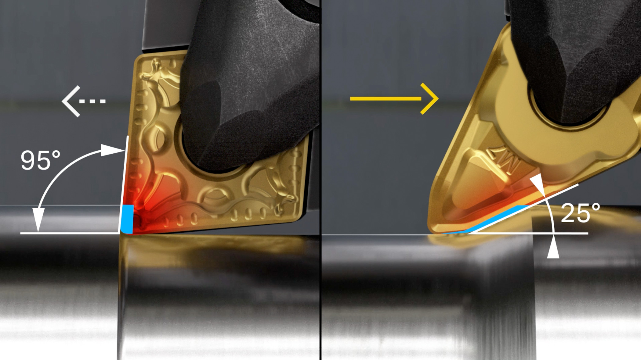
If the insert machines the workpiece at a near-to-90° angle, then the thickness of the chip will be equal to the feed rate (fn) — so, at an fn of 1 millimeter per revolution (mm/rev), the chip will be 1 mm thick. If we reduce the entry angle, the smaller we go and the thinner the chip thickness will be. We can increase the fn accordingly. So, for example, if we decrease the entry angle from 90° to 25° while increasing the fn from 0.25 up to 0.6 mm/rev, the chip thickness will remain the same. The result is more productive machining with the same levels of chip control.
To support this, Sandvik Coromant has created its PrimeTurning methodology, which includes machining with a small entry angle to give very high productivity and long tool life. The method allows customers to do turning in all directions, and, in doing so, they can achieve greater efficiency and productivity than is possible with conventional turning. PrimeTurning has resulted in increased productivity and longer-lasting tool life for customers.
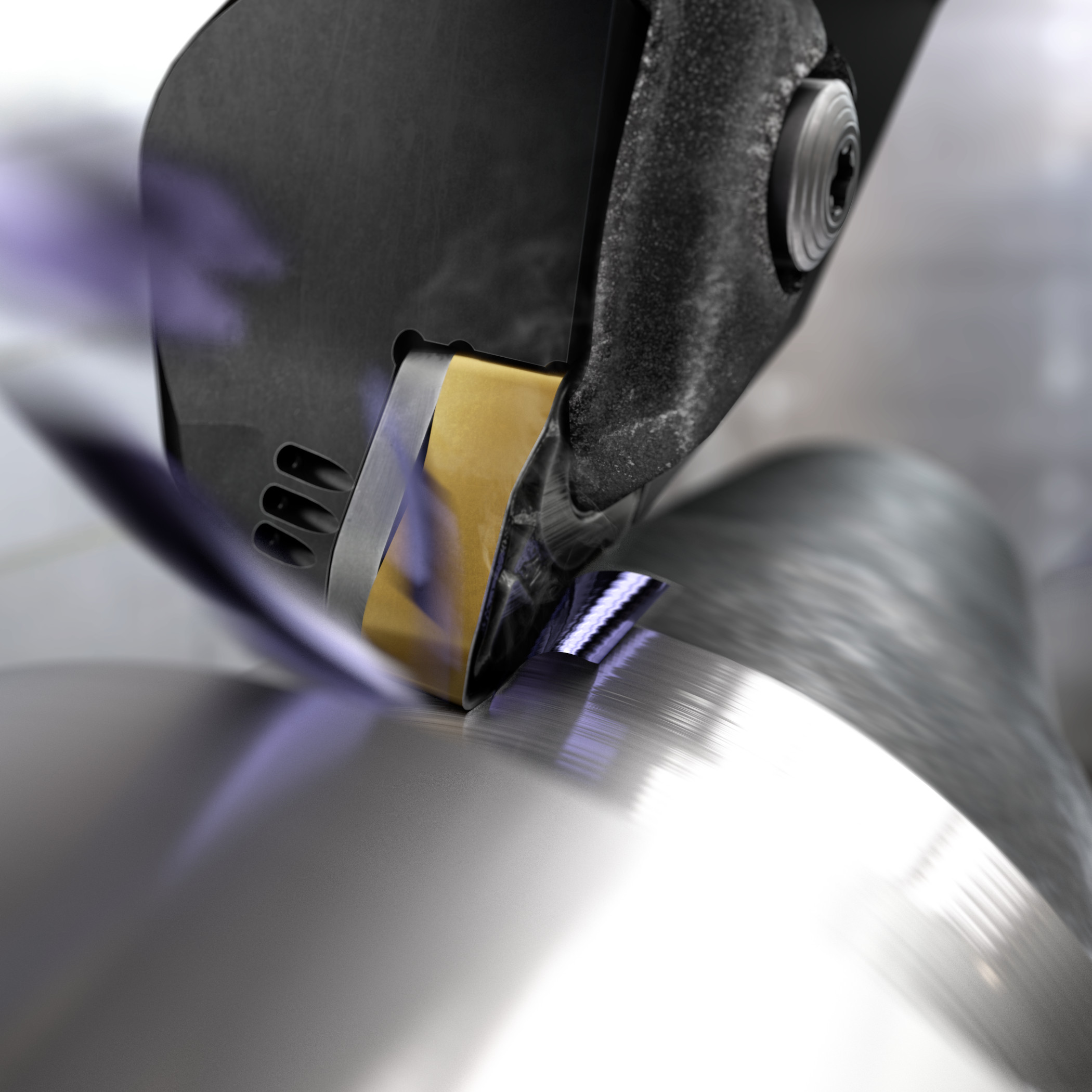
However, the process needs specific tooling to unlock these advantages. A conventional tool won’t allow the same levels of chip control or the right clearance angles and so will not work in practice. That is why Sandvik Coromant has developed CoroTurn PrimeTurning tools, of which the latest development is the second-generation CoroTurn Prime B-type inserts. The next-generation tool features double-sided negative inserts with four cutting edges designed for more cost-efficient machining, along with a new robust tip seat design and updated geometries. With these features, the tool can perform deeper cuts (mm), with higher machining (mm/rev) and fn speeds, plus improved chip control while machining high-strength steels and other tough steels.
This benefits productivity, but what about tool wear? This brings us to the design of the insert itself. With a conventional insert, machining at a smaller entry angle puts the majority of the heat and load into the corner of the insert, which also happens to be the insert’s weakest part with the least amount of carbide to absorb it. Instead, each next-generation CoroTurn Prime B-type insert has four cutting edges rather than two, with stronger corners. With more edges, more machining can be achieved with each insert, while heat and load is spread over a much bigger portion of the cutting edge.
The second-generation CoroTurn Prime B-type insert is also designed to overcome issues normally experienced when using inserts at a higher axial depth of cut (ap) and fn. That includes risks of overload and, at lower ap and fn, the risk of long chips. Machining operations can therefore be run at a much higher fn for improved chip control, stability, improved process security and better tool life. For manufacturers, meeting these higher standards of quality and efficiency can be met by implementing improvements at the machining stage.
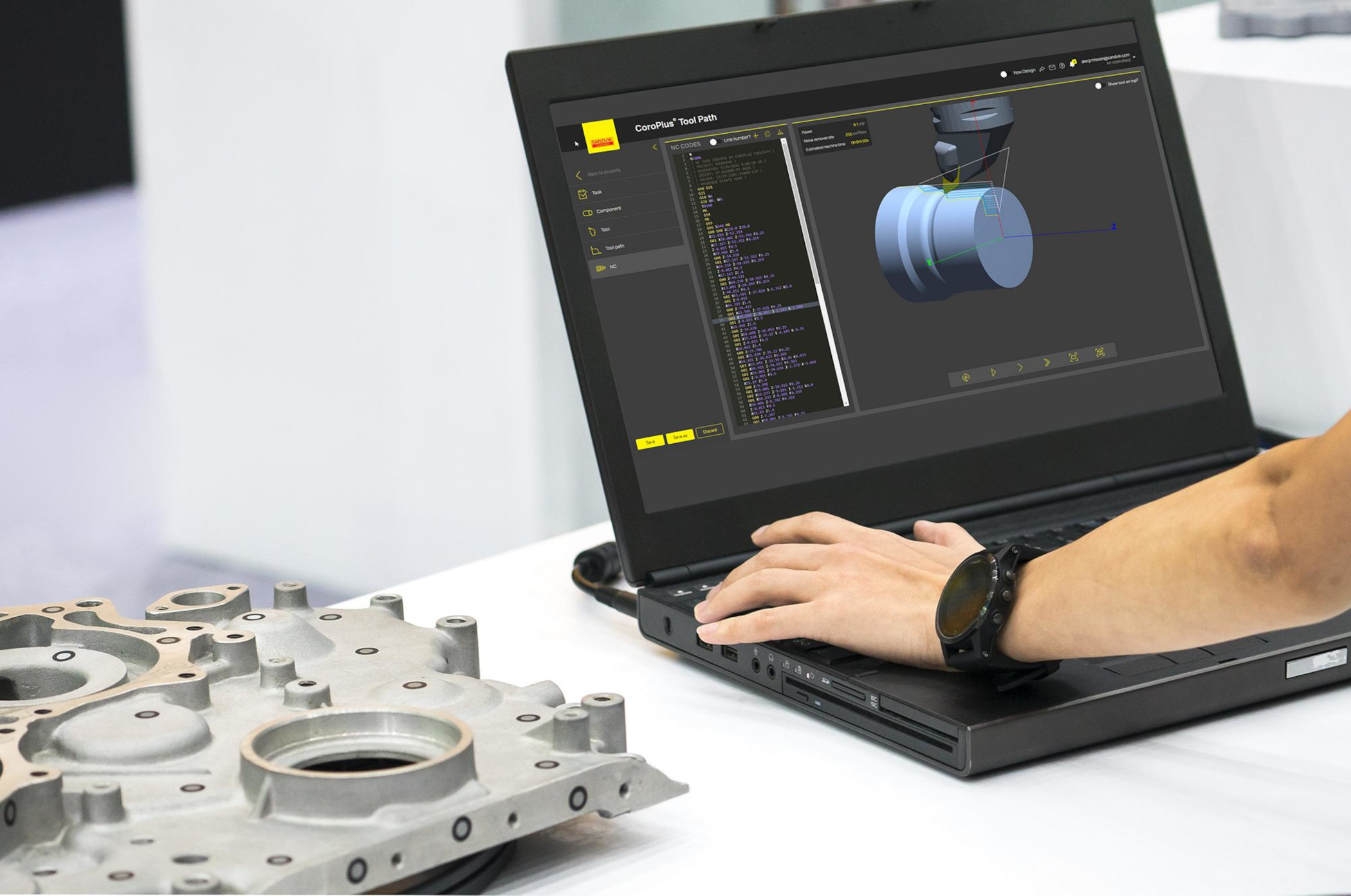
The advantages of the PrimeTurning method are further enhanced with CoroPlus Tool Path digital software. The software is a dedicated online tool path generator, which supplies programming numerical control (NC) codes and techniques to set up proper parameters and variables for a particular machining application. When this precise cutting data is used in combination with the CoroTurn Prime cutting tools, Sandvik Coromant customers have achieved smaller entering angles, efficient edge use and no chip jamming.
PrimeTurning also includes CAM software and programming support. That’s why Sandvik Coromant has built strong partnerships with Mastercam, TopSolid, Siemens NX, CAMWorks and GibbsCAM to ensure PrimeTurning and CoroPlus Tool Path are included within the biggest CAM software packages. Machine shops that don’t use CAM software can instead use the aforementioned CoroPlus Tool Path digital software to generate NC codes.
Enhanced productivity
In one case, a Sandvik Coromant customer in automotive wished to perform a roughing operation in an EMAG VSC 250 lathe, on a workpiece made from DIN 48CrMoV6-7 steel. The customer sought to achieve higher levels of productivity and tool life in its mass production but understood that adjustments in tool data would not be enough. That’s why, although primarily a roughing operation, the application would be performed with intermittent external turning and facing using the PrimeTurning method.
For this, Sandvik Coromant recommended the second-generation CoroTurn Prime B-type insert, which was tested against the customer’s existing inserts to assess the former tool’s performance advantages. Each tool was run with an identical 180 m/min cutting speed (vc) and axial depth of cut (ap) of 1.5 to 1.8 mm. However, CoroTurn Prime B-type gen 2 was run at a more-than-double higher fn of 0.65 mm/rev compared with just 0.3 mm/rev for the competing insert.
Although each inserts’ tool life was approximately the same, 9.58 min for the competing insert versus 10 min for the next-generation CoroTurn Prime B-type insert, there was a significant difference in productivity. The competing tool demonstrated a tool life of just 25 pieces (pcs) within a cutting time of 23 seconds per component. However, this was more than doubled by the Sandvik Coromant insert’s tool life of 50 pcs with just 12 seconds — roughly half the time — spent on each component. The second-generation CoroTurn Prime B-type insert also demonstrated more predictable edge wear and better chip control.
Going forward, Sandvik Coromant anticipates that its second-generation CoroTurn Prime B-type inserts will achieve similar benefits for other customers in automotive — including EV manufacturers. By using these inserts within the PrimeTurning method, manufacturers can save time when working with difficult-to-machine materials, along with the additional tool life benefits. With these machine tools and methods in place, automotive manufacturers will be able, paraphrasing Holweg, to diversify through leadership in design, technology or manufacturing excellence.
Contact Details
Related Glossary Terms
- clearance
clearance
Space provided behind a tool’s land or relief to prevent rubbing and subsequent premature deterioration of the tool. See land; relief.
- computer-aided manufacturing ( CAM)
computer-aided manufacturing ( CAM)
Use of computers to control machining and manufacturing processes.
- computer-aided manufacturing ( CAM)2
computer-aided manufacturing ( CAM)
Use of computers to control machining and manufacturing processes.
- cutting speed
cutting speed
Tangential velocity on the surface of the tool or workpiece at the cutting interface. The formula for cutting speed (sfm) is tool diameter 5 0.26 5 spindle speed (rpm). The formula for feed per tooth (fpt) is table feed (ipm)/number of flutes/spindle speed (rpm). The formula for spindle speed (rpm) is cutting speed (sfm) 5 3.82/tool diameter. The formula for table feed (ipm) is feed per tooth (ftp) 5 number of tool flutes 5 spindle speed (rpm).
- depth of cut
depth of cut
Distance between the bottom of the cut and the uncut surface of the workpiece, measured in a direction at right angles to the machined surface of the workpiece.
- feed
feed
Rate of change of position of the tool as a whole, relative to the workpiece while cutting.
- lathe
lathe
Turning machine capable of sawing, milling, grinding, gear-cutting, drilling, reaming, boring, threading, facing, chamfering, grooving, knurling, spinning, parting, necking, taper-cutting, and cam- and eccentric-cutting, as well as step- and straight-turning. Comes in a variety of forms, ranging from manual to semiautomatic to fully automatic, with major types being engine lathes, turning and contouring lathes, turret lathes and numerical-control lathes. The engine lathe consists of a headstock and spindle, tailstock, bed, carriage (complete with apron) and cross slides. Features include gear- (speed) and feed-selector levers, toolpost, compound rest, lead screw and reversing lead screw, threading dial and rapid-traverse lever. Special lathe types include through-the-spindle, camshaft and crankshaft, brake drum and rotor, spinning and gun-barrel machines. Toolroom and bench lathes are used for precision work; the former for tool-and-die work and similar tasks, the latter for small workpieces (instruments, watches), normally without a power feed. Models are typically designated according to their “swing,” or the largest-diameter workpiece that can be rotated; bed length, or the distance between centers; and horsepower generated. See turning machine.
- numerical control ( NC)
numerical control ( NC)
Any controlled equipment that allows an operator to program its movement by entering a series of coded numbers and symbols. See CNC, computer numerical control; DNC, direct numerical control.
- numerical control ( NC)2
numerical control ( NC)
Any controlled equipment that allows an operator to program its movement by entering a series of coded numbers and symbols. See CNC, computer numerical control; DNC, direct numerical control.
- shaping
shaping
Using a shaper primarily to produce flat surfaces in horizontal, vertical or angular planes. It can also include the machining of curved surfaces, helixes, serrations and special work involving odd and irregular shapes. Often used for prototype or short-run manufacturing to eliminate the need for expensive special tooling or processes.
- turning
turning
Workpiece is held in a chuck, mounted on a face plate or secured between centers and rotated while a cutting tool, normally a single-point tool, is fed into it along its periphery or across its end or face. Takes the form of straight turning (cutting along the periphery of the workpiece); taper turning (creating a taper); step turning (turning different-size diameters on the same work); chamfering (beveling an edge or shoulder); facing (cutting on an end); turning threads (usually external but can be internal); roughing (high-volume metal removal); and finishing (final light cuts). Performed on lathes, turning centers, chucking machines, automatic screw machines and similar machines.
- yield strength
yield strength
Stress at which a material exhibits a specified deviation from proportionality of stress and strain. An offset of 0.2 percent is used for many metals. Compare with tensile strength.


