

When Threading Drives You Nuts
A practical method for fitting custom preloading lock nuts to a Formula SAE wheel-hub design.
Watchful readers may remember my treatise on “Turning in a New Design,” which focused on new wheel hubs my students developed for their student-designed Formula SAE race car (published in the June/July 2026 issue). As promised in that report, this article will delve deeper into one operation that required us to thread the rearmost shank of the hub for a custom 2.875″-20 unified screw thread. So, here’s the method I used to fit the custom-made preloading lock nuts.
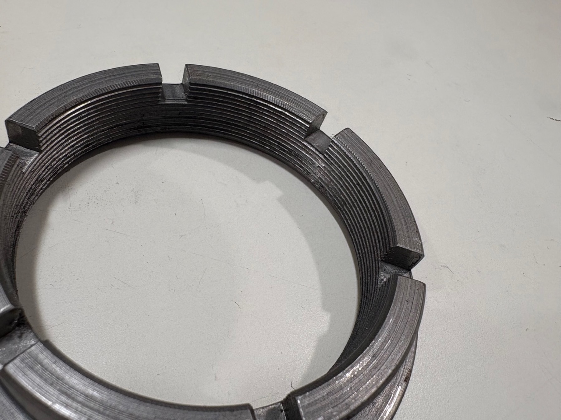
The lock nuts were of a castle-nut design dreamt up by another student on the same team as the hub’s designer and has only suffered a very few revisions over the years — a tribute to the success of the design. (See figures 1, 2 and 3 for an overview of the castle nuts.)
The students ordered me a generous length of 2.500″ nominal inside diameter (ID) drawn over mandrel (DOM) steel pipe sporting a 0.500″ wall thickness. This would give me plenty of material to cut away and guarantee that I was still able to finish a completed part. After turning the OD features, I then bored out the inside of the rings for the female thread. As a reminder, the formula I’ve used to great success is as follows: OD – 1″/N = Minor Diameter, where N is the number of threads per inch. For my parts, there are 20 threads per inch, so 1″/20 = 0.050″ and our thread OD is 2.875″. For the ID, I bored the parts to 2.825″ before setting my threading tool to cut the screw threads.
A Shameless Plug
Our CNC lathe has a very user-friendly tool wear compensation menu (see figures 4, 5 and 6). When doing the initial tooling setups, there was an option to “lie to” the machine and tell it that your cutter is slightly offset from where it really is. Regarding my threading operation, I told the machine that the tip of the tool was 0.007″ set back from the part’s ID. The control did the math and triangulation of the 29.5° lead angle in the background so I could simply tell the machine to dial in on the X axis alone.
The machine compensates on the fly, making programming and operation a breeze. All of this translates into being able to cut the female thread smaller than the desired finish size, and then advance the tool in by 0.0005″ increments in the offsets menu until I could get the wheel hubs (in this case, my plug gauge) to just barely thread in freely. The steel of the nut will wear the aluminum threads of the hub to settle into a perfect custom fit. I repeated this process five more times, making a spare matched set for a complete front hub assembly and a complete rear assembly.
After parting the rings off from stock, facing them to length, and back boring a relief, the parts were sent to our CNC mill to have the spanner slots cut into them. (See figure 7 for a fitted assembly.)
As an aside, we have had experience cutting some other types of threads on this machine. For example, the facilities maintenance crew at Lafayette College came to me asking if I could repair or replicate a tapered thread that had suffered some significant damage. We didn’t have a thread chaser or die for ½” NPT on hand, and instead of trying to borrow one or wait for one to show up, I decided to try to do it on our CNC lathe. After busting out and dusting off my Machinery’s Handbook and getting measurements, I was able to program our lathe to cut a tapered pipe thread. Testing the piece that I’d just spun up to an off-the-shelf fitting, we found that it fit perfectly. I used the same offset method as I had used for the steel lock nuts and advanced the tool tip by 0.0005″ until the fitting threaded on freely. No need for custom fit, as tapered pipe threads change diameter as you advance them, of course.
I hope these tips and tricks help you avoid “screwing up” an important threading job. As always, thanks for reading.
about the author: Robert Layng is an engineering technician/machinist at Lafayette College in Easton, Pennsylvania. He specializes in prototyping and practical design. He can be reached at layngr@gmail.com.
Review the print ads from this magazine to continue
This quick advertiser review unlocks the rest of the article and keeps the full-screen reader focused on the ads instead of the page chrome.
Advertisers included in this article experience
Print placements connected to this article
Eltool Corp.
Eltool Corp. print ad
Print ad listed on page 11 of the August 2026 issue.
View this placement in the issue recordMate Precision Technologies
Mate Precision Technologies print ad
Print ad listed on page 12 of the August 2026 issue.
View this placement in the issue recordMate Precision Technologies
Mate Precision Technologies print ad
Print ad listed on page 13 of the August 2026 issue.
View this placement in the issue recordContinue reading
August 2026
Podcast teaser: Be sure to catch up with Robert M. Layng on The Daily Grind podcast — presented by Cutting Tool Engineering — as he talks about machining operations with a new guest each week. Live, Monday mornings at 8 a.m. Eastern, and wherever you get your podcasts on Tuesday mornings.
Credit all images: Robert M. Layng
Figure 1.jpg Caption: Figure 1
Figure 2.jpg Caption: Figure 2
Figure 3.jpg Caption: Figure 3
Figure 4.jpg Caption: Figure 4
Figure 5.jpg Caption: Figure 5
Figure 6.jpg Caption: Figure 6
Figure 7.jpg Caption: Figure 7
Related

 MFGAxis Discussion
Be part of the shop-floor conversation
Like, save, or comment on this CTE story.
MFGAxis Discussion
Be part of the shop-floor conversation
Like, save, or comment on this CTE story.


MFGAxis Discussion