Cutting Time for Facing: Quick Guide
Facing time calculations change depending on whether spindle speed stays constant or surface speed is held constant.
Quick take: Facing time estimates change depending on whether a process runs constant RPM or constant surface speed. This page is most useful when it is paired with force, equation, and thermal-growth references during turning process planning.
Related references: Calculated Forces When Turning: Quick Guide, Understanding Cutting Equations, and Coefficient of Linear Thermal Expansion: Machining Guide.
Comparison between calculating cutting time when facing at a constant cutting speed vs. a constant rpm.
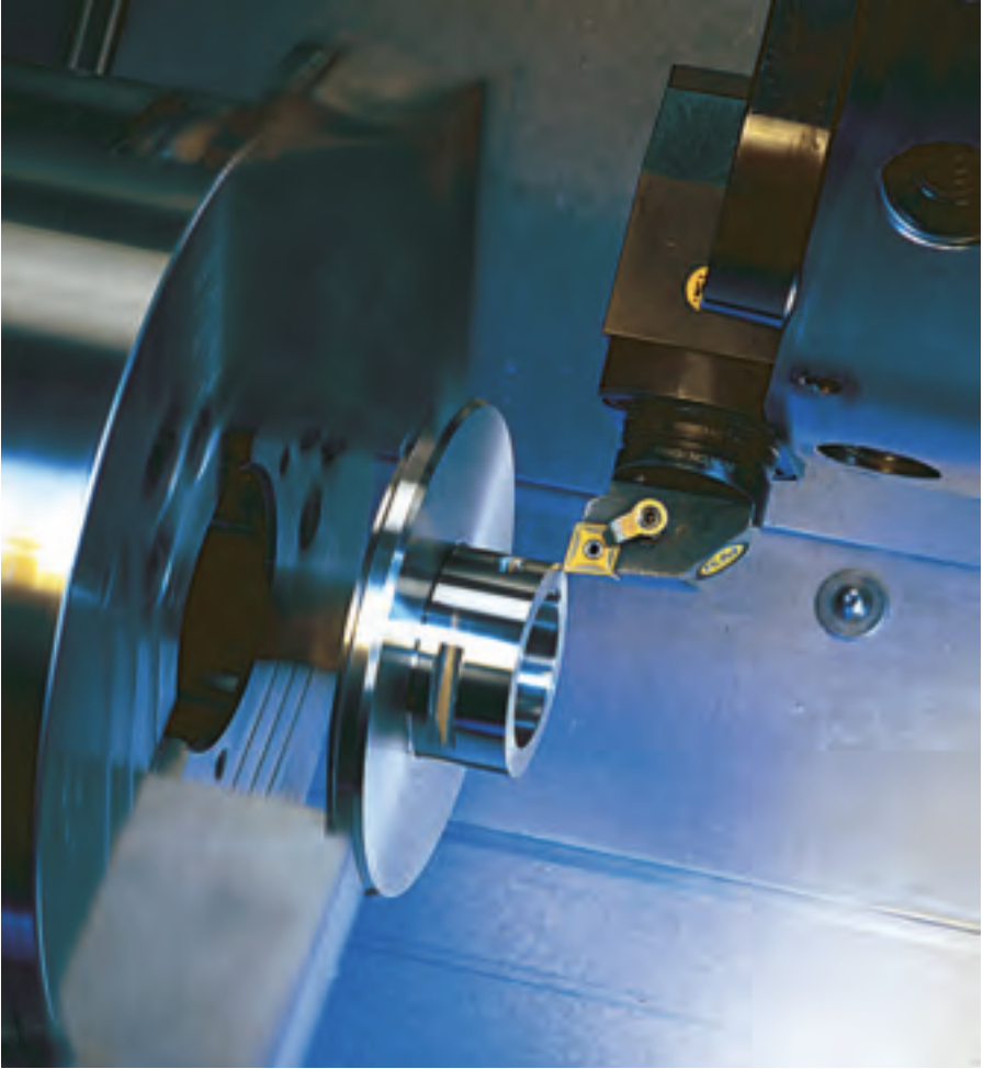
Facing being performed on a tubular workpiece. Image courtesy of Kennametal
Facing is a turning operation in which the workpiece is machined to its center. It involves moving the cutting tool perpendicular to the workpiece’s axis of rotation.
This operation can be performed at a constant surface speed (sfm, m/min.), which is recommended, or at a constant rotational speed (rpm), which is not recommended. Facing at a constant rpm decreases the cutting speed, because the diameter of the facing surface gradually decreases by the amount of a feed per revolution. The closer a cutting tool is to the center of a workpiece, the lower the cutting speed. It approaches zero at the center of a workpiece. A low cutting speed can cause built-up edge.
Cutting Time for Facing at Constant Cutting Speed
function calculateTimeConstantSpeed() { let diameter = parseFloat(document.getElementById(“diameter1”).value); let cuttingSpeed = parseFloat(document.getElementById(“cuttingSpeed”).value); let feedPerRev = parseFloat(document.getElementById(“feedPerRev1”).value); let radius = diameter / 2; let rpm = (12 * cuttingSpeed) / (Math.PI * diameter); let cuttingTime = radius / (feedPerRev * rpm); document.getElementById(“resultConstantSpeed”).innerText = “Cutting Time: ” + cuttingTime.toFixed(3) + ” minutes”;}
Formula: Cutting Time = (Initial Radius) / (Feed per Rev × RPM), where RPM = (12 × Cutting Speed) ÷ (π × Diameter)
Check out a more advanced Face Turning calculator here!
Therefore, end users have a dilemma: facing at a constant speed or a constant rpm. One way to calculate cutting time for facing is to use Web sites such as www.calculatoredge.com, which offers online calculators for engineers at no charge. Among the numerous categories, the lathe operations calculator provides a variety of calculations, including cutting time for facing. It calculates time for facing as a function of the constant rpm, workpiece diameter and feed per revolution. A representation of this calculator and an example of calculating time for facing at selected cutting parameters is shown in Figure 1.
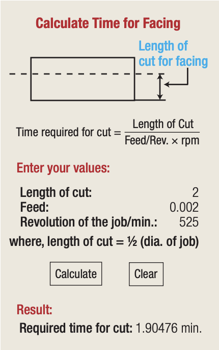
Figure 1. The lathe operations calculator page for cutting time for facing from www.calculatoredge.com. Courtesy of Calculator Edge
The following are the author’s comments regarding this calculator:
- The formula for calculating time for facing contains a value “Feed/Rev.,” which is confusing because it can be interpreted as feed divided by revolution. These two words should be replaced by fpr (feed per revolution), which is the most commonly used value.
- Revolution of the job/minute is an awkward definition of the machine tool’s spindle speed, which is defined in rpm.
- Required time for cut is given in five decimal points, such as 1.90476 minutes in this article’s example. Such precise “astronomical” accuracy is unjustified. Two (maybe three) decimal places are more than enough for practical accuracy.
In many of today’s CNC machines, most operations, including facing, are programmed using constant cutting speed, which is specified in sfm in inch mode or m/min. in metric mode. At constant cutting speed, a CNC lathe automatically applies the correct rpm based on the following formulas for inch and metric systems:
rpm = 12 × sfm ÷ (π × cutting diameter in inches),
rpm = 1,000 × m/min. ÷ (π × cutting diameter in millimeters).
Review the print ads from this magazine to continue
This quick advertiser review unlocks the rest of the article and keeps the full-screen reader focused on the ads instead of the page chrome.


MFGAxis Discussion