Flying-machine machining
Flying-machine machining
As aerospace materials have evolved, machine shops have had to use new tools and technologies in order to process them. The June 2016 CTE cover story delves into delamination of composites and other workpiece problems that challenge aerospace parts makers.
On the shop floor of aerospace job shop Protomatic, Dexter, Mich., a Haas VF-2SS vertical machining center armed with helical cutting tools was machining a billet of 1018 steel at a feed of about 250 ipm and a spindle speed around 2,000 rpm.
The company's manufacturing manager, John Donajkowski, ran the machine; he's been with the company for more than 30 years. Doug Wetzel, managing director, has been around even longer; the company was founded in 1971 by his father, Bill Wetzel. With Les Smith, senior machinist, another longtime employee, they demonstrated for CTE some of the ways that machining aerospace materials, particularly the challenging ones, has evolved in Protomatic's shop.
The shop does work for military and commercial primes and startups, and not only on airframes and engines but also missile systems, satellites and rocket engine components. About 40 employees work at its 30,500-sq.-ft. facility, which houses 30 machines for turning, milling and grinding. The company is getting started on MTConnect—an open manufacturing-communications protocol for connecting, monitoring and collecting data from an entire production floor—with five multiaxis machines. Every procedure for every job, Wetzel said, is flow-charted.

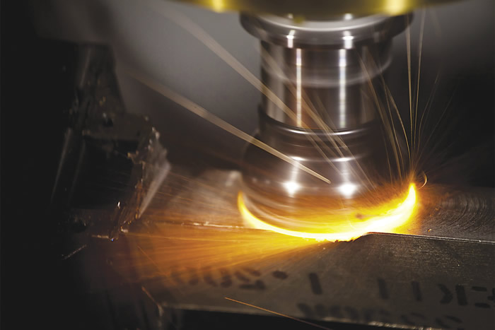
A KCRA-grade ceramic tool from Kennametal. Image courtesy Kennametal.

The list of workpiece materials includes plastics, aluminum, stainless steel, nickel-base superalloys and refractory alloys—high-temperature alloys that contain elements such as tungsten or molybdenum.
Although Protomatic is a family-owned, single-location shop, it can handle the tough stuff, Wetzel said. "We have electrical and mechanical engineers on staff who understand [how to machine challenging materials] and give guidance."
Sound Practices
That points up a difference from the old days, according to Wetzel. The newer alloys and what shops need to know to effectively cut them call for a different kind of expertise. "The technology is no longer understood from an intuitive sense," he said.
"For example—listen." Wetzel paused and looked at the Haas, which sang a smooth, low-volume tone as it cut.
"The machinists of yesteryear would start a machining operation, and they'd actually listen to it. They would be listening to the excitation frequency—the rpm of the cutting tool and how it responded," he said. "And if they were getting a harmonic, they knew they were at the wrong speed. So they would adjust their speeds or feeds to remove the harmonic until it was running smoothly. They had trained ears.

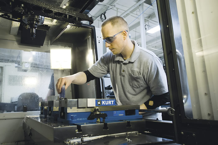
Machinist Joe Wetzel sets up an operation at Protomatic. Image courtesy Protomatic.

"The problem is, that only works if the relevant sounds are in the spectrum that humans can hear with the naked ear—and that's just no longer always the case," Wetzel added.
Now, technology is handling what used to take human skill.
"We use a frequency-analyzer microphone that allows us to analyze where the harmonics are occurring, and, based on what it tells us, we can adjust to a smoother speed and feed rate," he said. "And the machine tool makers are beginning to incorporate this kind of tool into their machines, with sensors and programs that listen and adjust as needed."
For Wetzel, this is an example of tribal knowledge and experience being supplemented, if not replaced, by technology to work with these materials.
"In some ways, we're making smarter systems while dumbing-down what the operator needs to know, so the machine [will be] making decisions on this automatically," he said. "Regarding harmonics, for example, you won't need a machinist with a trained ear; the machine itself will have the trained ear."
Hard Lessons
Improvements in cutting tools make a big difference in Protomatic's ability to compete, according to Wetzel. For example, Smith emphasized the advantages of 5-flute, helical cutting tools, especially when cutting Inconel. "The multiple flutes seem to do a lot better on the tougher materials," he said.

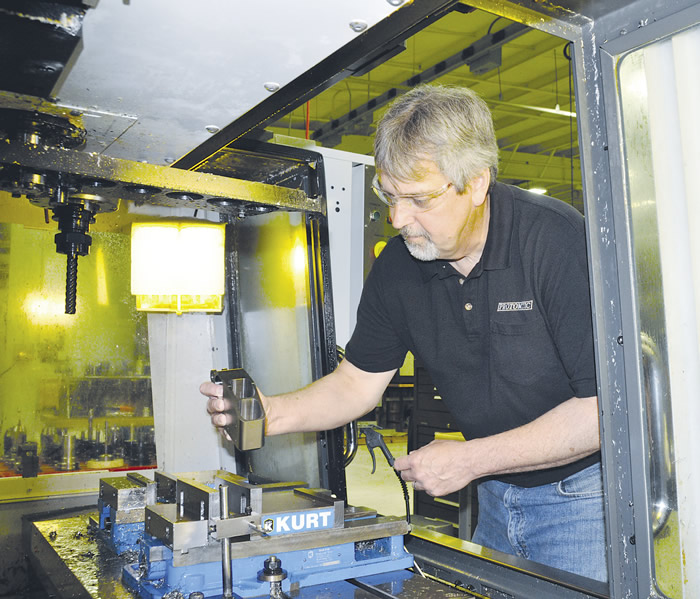
Les Smith, Protomatic's senior machinist, loads a rocket-engine component made of Inconel 718 into a Mazak Quick Turn Nexus 200-II M. Image courtesy Protomatic.

It's not only the geometry of the tool's cutting edge that concerns Protomatic, but also what is behind it. When machining deep pockets, "you want to keep your tool as short as possible for the sake of rigidity and to minimize vibration," Smith said. "We've learned that it's better to go part of the way down with a short tool, switch to a slightly longer one and then one that's longer yet," and optimize the speed and feed for each tool.
"We've found that reduced-neck tools work very well when you get down into the deeper pockets," Smith said, holding up a tool, "so that the neck isn't dragging on the wall when you get deep."
These best-practices were developed after producing what Wetzel called "problem-child parts," including actuator components and parts for rocket-engine fuel systems.
The Best Path Forward
Along with changes in the tools themselves, improvements in howtoolpaths are plotted have been achieved. For more than a decade, Protomatic has been using toolpath-generating and optimizing software programs such as Volumill from Celeritive Technologies and Truemill from Surfcam, according to Donajkowski. "These programs eliminate the machining of air," he said. "They keep the tool engaged with the material at all times, so there's no wasted motion."
One wants to keep a carbide tool engaged continuously because "carbide is a material that doesn't like to be shocked," Wetzel explained. "If you're shocking and vibrating a carbide tool with unnecessary impacts against the material and chirping it in corners, you're going to create oscillations and opportunities to chip the tool."
Before the advent of such programs, "we were sort of making our own paths with those dangers in mind," Donajkowski said. "These programs certainly make it easier."

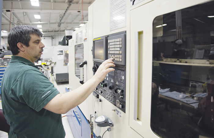
Manufacturing manager John Donajkowski sets up a machining operation on Protomatic's Tsugami TMA8 multitask turning center. Image courtesy Protomatic.

He recalled how such programs came into the shop. Decades ago, "the older, more experienced machinists showed us their ways of machining, what to watch out for—and listen for," he said. "But we picked up on computers faster than they did, and we started to learn and then teach them about these new kinds of software programs.
"And now with the new generation coming in, it's basically the same thing," he finished. "They're going to teach us new tricks."
Ceramic Tool Tips
One relatively "new trick" for cutting the hard and high-temperature nickel-base superalloys used to make aerospace engine components is ceramic tools. Matthieu Guillon is the global portfolio manager of advanced materials for Kennametal Inc., Latrobe, Pa. He has watched as these superalloys have allowed aircraft engines to run at higher temperatures and said ceramic tools can offer an advantage to supply-chain job shops that are tasked with cutting them—but only when applied correctly. This is because ceramics are brittler than carbides, he noted.
"There are important things machinists need to keep in mind to maximize the performance and life of their ceramic tools," Guillon said. One is to be mindful of how to keep them cool when milling and turning. Kennametal's double-sided KCRA-grade (Kennametal ceramic round air) ceramic platform is meant to be run dry, and has a feature in the clamping system that delivers air flow to the insert's cutting edge to improve chip flow and insert life. "Regular-air or cold-air blasts are applied for better chip evacuation," he said.
But where milling with ceramics is done dry, turning with ceramics requires coolant—but only the right amount. "Ceramics need heat to run well, meaning too much coolant in turning can actually be counterproductive," Guillon said. "You need to establish a range based on your equipment, toolholder and coolant delivery. High-pressure coolant systems of 1,000 psi will work well with catalog parameters in clearing chips and keeping the pocket clean. On some dedicated equipment, ultrahigh-pressure coolant will be applied at increased parameters."
Maintaining rigidity at the spindle connection is also critical, Guillon said.
Machine tool builders offer specialty milling and turning centers that feature improved stiffness and damping on spindles and sizable machine structures, which minimize undesirable vibrations that deteriorate part quality and shorten tool life. "Although these advances have added to greater productivity, the weakest point has often been the spindle connection itself," he said.
"The most critical parameters of a taper-face spindle connection are the clamping force and radial interference. Maximizing clamping force and selecting appropriate values of interference can further improve connection rigidity," Guillon said.
Cool Freedom
For David Aly, national aerospace specialist at OSG USA Inc., the two biggest issues for aerospace suppliers trying to effectively machine high-temperature alloys are tool wear and workhardening from heat buildup. This requires a free-cutting tool that exerts less pressure on the part, he said. "The idea is to put more of the heat into the chip instead of the tool or the material."
He offered the OSG EXOPRO UVX-Ni endmill as an example. "It has a free-cutting geometry, but it has a strong cutting edge. It's a variable-index and a variable-helix-type endmill, and that helps to eliminate harmonics and, therefore, chatter."
When drilling superalloys, improved coolant delivery, along with advanced cutting geometries, are making a difference for OSG customers, Aly said, adding that the EXOCARB WDO SUS drill illustrates the point. Targeted for drilling titanium, stainless and duplex stainless, the carbide drill has coolant holes designed to reportedly provide 30 to 40 percent more coolant to the cutting edge than other through-coolant drills.
Its other advantage is its cutting edge and flute form. "The drill forms the chips to be smaller so they can be eliminated from the hole more easily," Aly explained. "Customers say they really like it because they can use it successfully in areas where they have had issues before."
Flexibility Factor
Back at Protomatic, the component being machined from 1018 steel was quickly finished. For the next task on the Haas, "we're going to 17-4 steel, which we can machine at about 100 ipm," Donajkowski said.

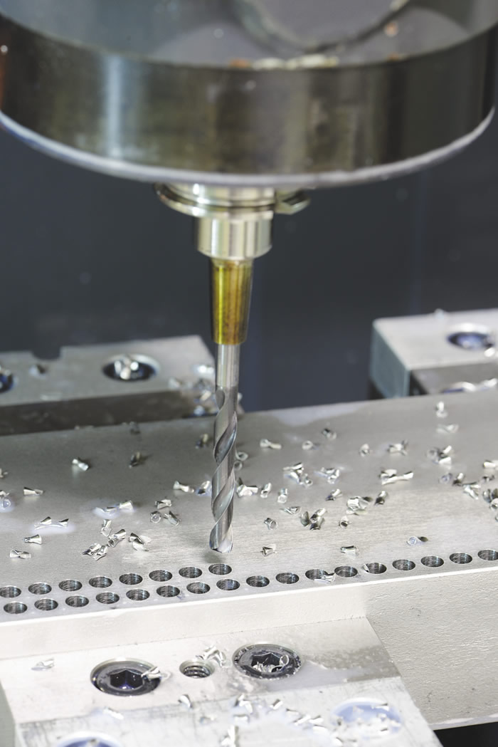
OSG USA's WDO SUS coolant-through drill is for cutting titanium and hardened stainless steel. Image courtesy OSG USA.

Wetzel described the company's commitment to training, QC and process-improvement initiatives as a must for an aerospace supplier. And an important component in all of those is keeping up with processes and technologies that can increase customer value, he said.
What the right tools and toolpaths also allow is greater flexibility, he explained. With them, even when machining challenging metals on a light-duty VMC, Protomatic can meet its customers' quality, turnaround and cost requirements, he said.
"We can do lots of fast, light cuts—and we can compete."

From metal to composites
While the move from relatively easy-to-machine grades of aluminum and steel to high-strength, high-temperature alloys is one big adjustment that many aero machine shops have had to make, an equally big move for many has been from metals to composites.
High-flying military projects, such as the F-35 Lightning II fighter, and commercial ones, such as the Boeing 787, have garnered mainstream media attention for their use of carbon composites; in their wake, more components than ever are being made for a variety of aero platforms—and so suppliers have had to step up.
Even after decades of composites use in the industry, OSG USA's David Aly still finds machinists who haven't quite completely internalized the differences between metals and composites.
"There are a lot of machinists who grew up in the metalcutting-only age of machine shops, and, who, when they are moved to the composite-machining end of a shop, don't always understand why they can't use the same tooling," Aly said.

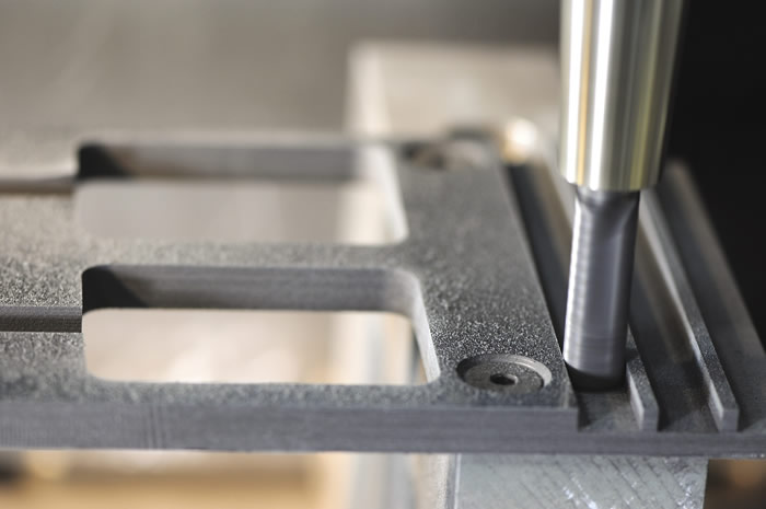
OSG's BNC router machines a composite material. Image courtesy OSG USA.

Composite components are most commonly made from prepreg—resin-impregnated carbon-fiber tows that are
layered and then cured into a lightweight, strong material. But those layers can't be cut in the same way as a solid piece of metal.
"In metalcutting, of course, you don't have those layers. In composites you layer one laminate on top of another. But if the composite material heats up too much or isn't cut properly, the layers start coming apart," Aly said. "That's delamination, and we don't want that."
He said: "We get called in when a shop is having tool life issues or quality issues resulting from the wrong tool being used. We see delamination of materials, splintering, burrs, fiber pullout—things along those lines. Usually, it's just a matter of applying the right tool for the situation."
The metalcutting legacy of many composite-machining shops can manifest in other ways as well. "When machinists bring that metalcutting mindset to composites, sometimes they think about the tool cost more than about the tool life and the overall cost of putting a part on the floor," Aly said. "A diamond product may be more expensive than what they would normally think about using. We have to explain and prove to the customer that they may pay a little more for the tool, but they're going to get a lot longer tool life, and, in the end, the per-piece cost is going to be less."
—M. Anderson

Contributors
Protomatic
(734) 426-3655
www.protomatic.com
Kennametal Inc.
(800) 446-7738
www.kennametal.com
OSG USA Inc.
(800) 837-2223
www.osgtool.com


