This article is about measuring 60 degree screw threads. In particular, I will talk about using thread measuring wire gauges. This is kind of a lost art in the machine shop world, but it is a handy, accurate and versatile way to measure pitch diameters on outside threads. Three wires of the same diameter are used with a micrometer to get a measurement of the threads pitch diameter. Figure 1 shows how this is done.
A little math is required with this trick. From a machinery handbook get the major diameter range for the thread being measured. The wires come in sets of 16 or so different diameter wires. A chart accompanies the set and shows what thread pitches are measured with each wire diameter. A factor listed on the chart is added to the major diameter to get the micrometer reading that is being sought.
For example, the thread being measured in Figure 1 is 9/16-18 UNF. From the chart that comes with the wires, the 0.0395" diameter wire is selected and the factor is 0.0343. So, 0.561/0.552 major diameter + 0.034 = 0.595/0.586 micrometer reading. And there you have it. Note that the 0.0343 wires are used with any 18 pitch thread on any major diameter. The set of 48 wires that I use will measure any English thread pitch from 31/2 to 40. Like I said, thread measuring wires are versatile.
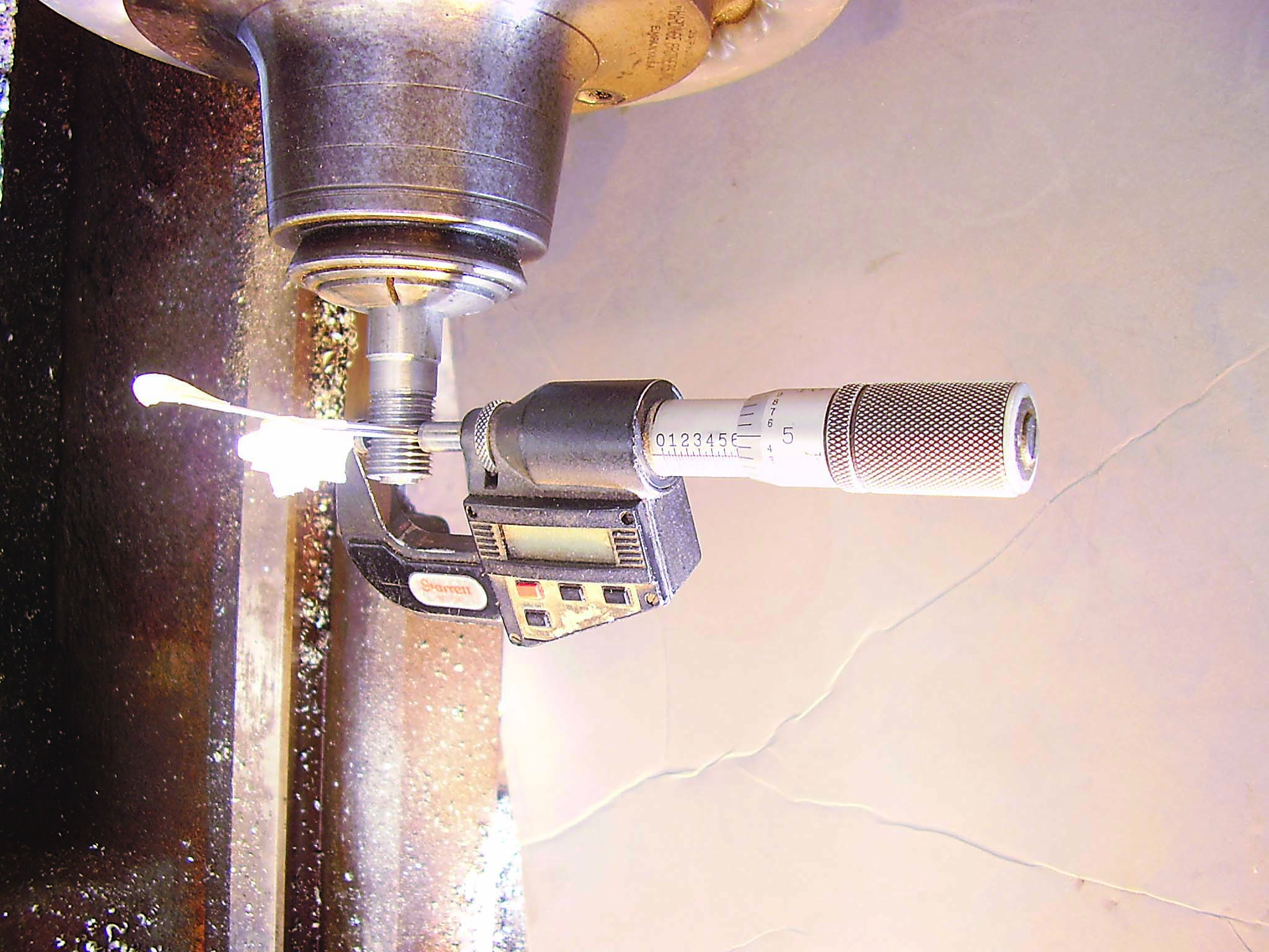
This thread is being made on a lathe with a single point tool and gauged in process.
The wires are placed against the flanks of the thread, two wires beside each other on top of the thread, and one wire is placed on the bottom side of the thread in the thread groove radially between the first two wires. The micrometer holds the wires to the thread and measures the distance between the outside surfaces of the wires.
The process is simple and takes just a little manual dexterity. First adjust the mike so distance between the spindle and anvil is a little bigger than the measurement range that is required. In this case something like 0.650". Put the first two wires on the top of the thread and hold them against the thread with the spindle of the mike and the barrel of the mike pointed up. Let gravity work with you. Then place the third wire in position and adjust the mike for the reading. When the barrel of the mike is perpendicular to the thread axis and stable on the part without holding it with your hand, that’s it.
In the picture, there is a little piece of masking tape folded on the end of each wire. I find the wires easy to handle this way, but the main reason for the tape is if I drop a wire down into the chip pan in the lathe, I won’t have the needle in the haystack problem. That can be a pain. And if the lathe has a coolant sump under a screen in the chip pan, goodbye wire.
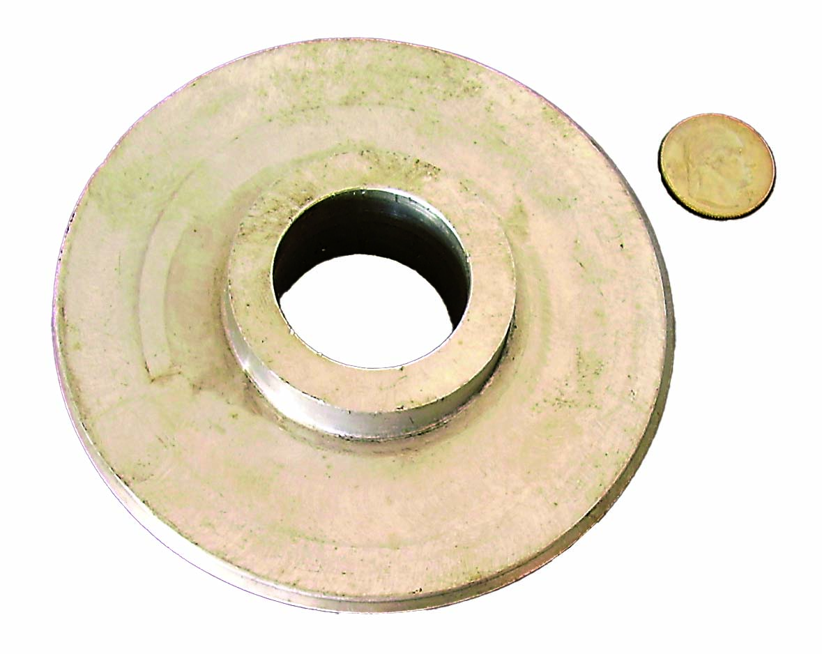
Of course, go/no-go plug or ring gauges are easier to use, but what if you need to make a thread that requires a custom gauge? Figure 2 shows a solution to that problem. It is a go plug gauge I made for a 41/2 -8" thread. I made that plug gauge on a lathe using thread wires to measure the thread.
I hope you find this information useful.
Related Glossary Terms
- coolant
coolant
Fluid that reduces temperature buildup at the tool/workpiece interface during machining. Normally takes the form of a liquid such as soluble or chemical mixtures (semisynthetic, synthetic) but can be pressurized air or other gas. Because of water’s ability to absorb great quantities of heat, it is widely used as a coolant and vehicle for various cutting compounds, with the water-to-compound ratio varying with the machining task. See cutting fluid; semisynthetic cutting fluid; soluble-oil cutting fluid; synthetic cutting fluid.
- lathe
lathe
Turning machine capable of sawing, milling, grinding, gear-cutting, drilling, reaming, boring, threading, facing, chamfering, grooving, knurling, spinning, parting, necking, taper-cutting, and cam- and eccentric-cutting, as well as step- and straight-turning. Comes in a variety of forms, ranging from manual to semiautomatic to fully automatic, with major types being engine lathes, turning and contouring lathes, turret lathes and numerical-control lathes. The engine lathe consists of a headstock and spindle, tailstock, bed, carriage (complete with apron) and cross slides. Features include gear- (speed) and feed-selector levers, toolpost, compound rest, lead screw and reversing lead screw, threading dial and rapid-traverse lever. Special lathe types include through-the-spindle, camshaft and crankshaft, brake drum and rotor, spinning and gun-barrel machines. Toolroom and bench lathes are used for precision work; the former for tool-and-die work and similar tasks, the latter for small workpieces (instruments, watches), normally without a power feed. Models are typically designated according to their “swing,” or the largest-diameter workpiece that can be rotated; bed length, or the distance between centers; and horsepower generated. See turning machine.
- micrometer
micrometer
A precision instrument with a spindle moved by a finely threaded screw that is used for measuring thickness and short lengths.
- pitch
pitch
1. On a saw blade, the number of teeth per inch. 2. In threading, the number of threads per inch.
Author

Brandt Taylor is owner of Berlin, Massachusetts-based Taylor Engineering, a machine shop.