The American National Standard (ANSI B212.4-2002) establishes a detailed identification system for indexable inserts used in single-point and multiple-point cutting tools. Published on October 29, 2002, this standard ensures consistency, precision, and compatibility in machining operations. By defining key insert characteristics, the system has become essential for selecting the correct tools for various machining applications.
Earlier editions of this standard include:
- ANSI B212.12.1-1995, focusing on indexable screw-on inserts with partly cylindrical fixing holes.
- ANSI B212.12-1991, detailing turning tools and commonly used indexable inserts.
This guide provides an in-depth explanation of the ANSI B212.4-2002 standard, its 10 identification positions, and additional insights into Kennametal's chip breaker identification system, along with their applications in modern machining.
Overview of the 10 Identification Positions
According to the ANSI B212.4-2002 standard, the identification system for indexable inserts includes 10 positions, each denoted by a capital letter. These positions define the insert's key characteristics in the following order:
1. Shape
2. Clearance
3. Tolerance class
4. Type
5. Size
6. Thickness
7. Cutting-point configuration
8. Edge preparation
9. Hand
10. Facet size
These characteristics ensure that the right insert is selected for specific machining operations, enhancing tool performance, durability, and machining precision.
1. Understanding Indexable Insert Shapes (ANSI B212.4-2002)
The first position in the ANSI B212.4-2002 standard identifies the shape of indexable inserts, a crucial characteristic for machining applications. There are 16 standard shapes, each designated by a capital letter. These shapes ensure compatibility with different machining tools and workpiece requirements.
The standard shapes are:
- A – Parallelogram 85°
- B – Parallelogram 82°
- C – Diamond 80° (Rhombic)
- D – Diamond 55° (Rhombic)
- E – Diamond 75° (Rhombic)
- H – Hexagon 120°
- K – Parallelogram 55°
- L – Rectangle 90°
- M – Diamond 86° (Rhombic)
- O – Octagon 135°
- P – Pentagon 108°
- R – Round
- S – Square 90°
- T – Triangle 60°
- V – Diamond 35° (Rhombic)
- W – Trigon 80°
Figure 1: Kennametal Inc. Insert Shape Identification System. Courtesy of Edmund Isakov.
Why Shape Matters
- Application Suitability: Different shapes are optimized for turning, milling, or other operations.
- Chip Control: Insert shapes influence chip flow, minimizing clogging and improving efficiency.
- Surface Finish: The choice of shape can impact the quality of the final machined surface.
2. Clearance Angles and Relief Values in Indexable Inserts
The second position in the ANSI B212.4-2002 standard defines the relief angle, a critical feature for proper tool clearance and efficient cutting performance. Relief angles reduce friction between the insert and the workpiece, improving chip evacuation and reducing heat during machining.
Understanding Relief Angles
These angles are the difference from 90° measured in a plane normal to the cutting edge. They are generated by the angle between the flank and the top surface of the insert. This design ensures smooth operation and minimizes tool-workpiece interference.
Standard Relief Angles
The nine standard relief angles, as per ANSI B212.12-1991, are:
- A – 3°
- B – 5°
- C – 7°
- D – 15°
- E – 20°
- F – 25°
- G – 30°
- N – 0°
- P – 11°
Addition in the 2002 Standard
The ANSI B212.4-2002 standard introduced a new relief angle:
- O – Designed for advanced indexable inserts used in modern machining.
Why Clearance (Relief Angle) Matters
- Cutting Performance: Ensures smooth operation by minimizing cutting resistance.
- Tool Longevity: Reduces heat and wear on the insert, prolonging its operational life.
- Surface Finish: Improves the quality of machined surfaces by reducing tool pressure.
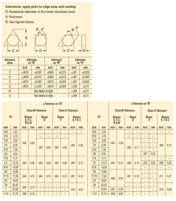
Figure 2: Kennametal Inc. Tolerance Identification System. Courtesy of Edmund Isakov.
3. Tolerance Classes and Dimensional Accuracy of Indexable Inserts
The third position in the ANSI B212.4-2002 standard denotes the tolerance class of an indexable insert. Tolerances control the indexability, ensuring inserts fit securely and perform reliably in various machining applications. Each tolerance class is represented by a capital letter, indicating the allowable dimensional deviation from nominal values.
Standard Tolerance Classes
There are 14 tolerance classes in the ANSI standard:
A, B, C, D, E, F, G, H, J, K, L, M, U, and N.
These classes ensure compatibility across different insert geometries, toolholders, and machining operations.
Dimensional Tolerances (± From Nominal)
Tolerances on specific dimensions are further denoted by letters A, B, and T, referring to:
- Dimension A: The nominal inscribed circle (I.C.) of the insert.
- Dimension B: The height of the insert:
- For pentagon, triangle, and trigon shapes, this is the distance between one side and the opposite corner.
- For other polygons, Dimension B is the distance measured along the bisector of the rounded-off corner angle, tangent to a gage roll of nominal I.C. size (see Figure 2).
- Dimension T: The thickness of the insert.
For example, if the tolerance letter is H, tolerances on dimensions (± from nominal) are as follows:
- Dimension A: ±0.0005 inches
- Dimension B: ±0.0005 inches
- Dimension T: ±0.001 inches
These precise tolerances are critical for ensuring proper insert alignment, toolholder fit, and machining accuracy.
Practical Example
A tolerance class of H would indicate a high level of accuracy, making it suitable for applications requiring fine detail and precision machining. In contrast, tolerance classes such as M or N may allow for looser tolerances in less demanding operations.
Why Tolerance Class Matters
- Precision Machining: Enables consistent and accurate cuts by ensuring the insert fits securely.
- Interchangeability: Standardized tolerances allow inserts to be used across multiple tools.
- Operational Efficiency: Reduces the risk of misalignment or tool failure, leading to improved performance.
Figure 3: Tolerance Chart for Indexable Inserts. Courtesy of Kennametal Inc.
4. Type of Indexable Inserts: ANSI B212.4-2002 Guide
The fourth position in the ANSI B212.4-2002 standard is a capital letter denoting differences in the design of the insert, such as the existence of fixing holes, countersinks, and special features on rake surfaces. This classification ensures compatibility with toolholders and supports efficient machining for various applications.
Standard Insert Types
There are 15 standard types in insert design, each represented by a letter. These types determine the insert's specific features and functionalities (Figure 4):
- A – With hole, without chip grooves.
- B – With hole, without chip grooves, and one countersink (70°-90°).
- C – With hole, without chip grooves, and two countersinks (70°-90°).
- F – Without hole with chip grooves on two rake faces.
- G – With hole and chip grooves on two rake faces.
- H – With hole, one countersink (70°-90°), and chip groove on one rake face.
- J – With hole, two countersinks (70°-90°), and chip grooves on two rake faces.
- M – With hole and chip groove on one rake face.
- N – Without hole, without chip grooves.
- Q – With hole, without chip grooves, and two countersinks (40°-60°).
- R – Without hole with chip groove on one rake face.
- T – With hole, one countersink (40°-60°), and chip groove on one rake face.
- U – With hole, two countersinks (40°-60°), and chip grooves on two rake faces.
- W – With hole, without chip grooves, and one countersink (40°-60°).
- X – With dimensions or details requiring detailed explanation, a sketch, or additional specifications.
These variations allow machinists to select the appropriate insert type based on their specific toolholder requirements and machining applications.
Applications of Insert Types
- A, B, C: Ideal for rigid setups that require strong clamping without chip grooves, typically used in general-purpose turning or milling.
- F, G, H, J: Suitable for operations where chip control is critical due to the inclusion of chip grooves, improving efficiency in high-speed machining.
- N, Q, R, T, U, W: Specialized types for unique machining setups, offering versatility in handling different materials and cutting conditions.
- X: Custom-designed inserts for highly specialized applications requiring detailed specifications.
Figure 4: Kennametal Inc. Insert Type Identification System. Courtesy of Edmund Isakov.
5. Size of Indexable Inserts: ANSI B212.4-2002
The fifth position in the ANSI B212.4-2002 standard is a significant one- or two-digit number that indicates the size of the inscribed circle (I.C.) for indexable inserts with a true I.C. This measurement is crucial for ensuring compatibility with toolholders and achieving precise machining performance.
Understanding Inscribed Circle (I.C.) Size
For shapes such as Round, Square, Triangle, Trigon, Pentagon, Hexagon, Octagon, and Diamond, the size refers to the number of eighths of an inch in the nominal diameter of the I.C.
Whole Number Sizes (One Digit):
When the I.C. size is a whole number, it is represented by a single digit:
- 1 – 1/8"
- 2 – 1/4"
- 3 – 3/8"
- 4 – 1/2"
- 5 – 5/8"
- 6 – 3/4"
- 7 – 7/8"
- 8 – 1"
- 10 – 1-1/4"
Fractional Sizes (Two Digits):
For I.C. sizes that are not whole numbers, a two-digit number is used, carried to one decimal place. Examples include:
- 1.2 – 5/32"
- 1.5 – 3/16"
- 1.8 – 7/32"
- 2.5 – 5/16"
Size Measurement for Rectangular and Parallelogram Inserts
For rectangular and parallelogram inserts, the I.C. size is replaced by width and length dimensions, which are also denoted by two-digit numbers:
- First Digit: Indicates the width in eighths of an inch.
- Second Digit: Indicates the length in fourths of an inch.
Example:
A rectangular insert with a width of 3/8 inch and a length of 1 inch would have a size designation of 32.
Applications of Proper Size Selection
- Toolholder Compatibility: Ensures the insert fits securely, avoiding misalignment during operation.
- Precision Machining: Correct sizing optimizes cutting performance and reduces errors.
- Flexibility: Enables machining across various applications, from delicate finishing to heavy-duty operations.
- Inventory Management: Standardized sizes simplify tooling decisions and minimize confusion.
Choosing the Right Insert Size
When selecting an insert size:
- Verify the toolholder’s specifications to match the I.C. size or width/length dimensions.
- Consider the application requirements—smaller inserts for fine-detail work or larger sizes for robust operations.
- Ensure the size aligns with the material's cutting requirements to optimize performance and longevity.
Why Size Matters
Proper insert size is a fundamental factor in machining success. It not only impacts toolholder compatibility but also enhances the precision and efficiency of cutting operations. Selecting the right size reduces setup times, minimizes errors, and prolongs tool life, making it an essential consideration in machining processes.
6. Thickness of Indexable Inserts: ANSI B212.4-2002
The sixth position in the ANSI B212.4-2002 standard denotes the thickness of the indexable insert. This measurement, represented by a one- or two-digit number, indicates the number of sixteenths of an inch in the thickness. Thickness plays a crucial role in ensuring the insert's structural integrity, toolholder compatibility, and overall machining performance.
Whole Number Thickness (One Digit)
When the thickness is a whole number, it is represented by a single digit. Standard thickness values are:
- 1 – 1/16"
- 2 – 1/8"
- 3 – 3/16"
- 4 – 1/4"
- 5 – 5/16"
- 6 – 3/8"
- 7 – 7/16"
- 8 – 1/2"
- 9 – 9/16"
- 10 – 5/8"
Fractional Thickness (Two Digits)
For thicknesses that are not whole numbers, a two-digit number carried to one decimal place is used. This allows for precision in specifying the insert’s dimensions. Examples include:
- 1.2 – 5/64"
- 1.5 – 3/32"
- 2.5 – 5/32"
- 3.5 – 7/32"
Importance of Thickness in Machining
- Structural Stability: Thicker inserts provide better support and reduce the risk of deformation under high cutting forces.
- Toolholder Fit: Correct thickness ensures a secure and vibration-free fit within the toolholder.
- Machining Versatility: Adjusting thickness allows for compatibility with different applications, from fine-detail work to heavy-duty machining.
Applications of Proper Thickness Selection
- Fine Machining: Thin inserts (e.g., 1–3 sixteenths) are ideal for applications requiring high precision and minimal cutting forces.
- Heavy-Duty Operations: Thicker inserts (e.g., 6–10 sixteenths) withstand higher forces and are best suited for robust machining tasks like roughing.
- Intermediate Applications: Mid-range thicknesses (4–5 sixteenths) balance precision and durability, making them versatile for general-purpose machining.
Choosing the Right Thickness
To select the appropriate insert thickness:
- Match Toolholder Specifications: Ensure the insert thickness aligns with the toolholder’s pocket depth.
- Consider Cutting Forces: Choose thinner inserts for low-force operations and thicker inserts for heavy-duty tasks.
- Optimize for Material Properties: Softer materials may require thinner inserts for precision, while harder materials benefit from thicker inserts for durability.
Why Thickness Matters
Thickness directly influences an insert’s ability to perform in demanding machining environments. Proper thickness reduces vibrations, enhances cutting stability, and prolongs the tool’s lifespan, making it a vital factor in achieving consistent machining results.
7. Cutting-Point Configurations in Indexable Inserts: Radius and Facet Designations
The seventh position in the ANSI B212.4-2002 standard specifies the cutting-point configuration of an indexable insert, which can be either a radius or a facet. This characteristic directly influences machining precision, surface finish, and tool longevity.
Radius Designations
When the cutting-point configuration is a radius, it is represented by a numerical value that indicates the size of the corner radius in sixty-fourths of an inch. Below are the standard radius designations:
- 0 – Sharp corner (maximum radius of 0.002")
- 0.2 – Radius of 0.004"
- 0.5 – Radius of 0.008"
- 1 – Radius of 1 ⁄ 64"
- 2 – Radius of 1 ⁄ 32"
- 3 – Radius of 3 ⁄ 64"
- 4 – Radius of 1 ⁄ 16"
- 5 – Radius of 5 ⁄ 64"
- 6 – Radius of 3 ⁄ 32"
- 7 – Radius of 7 ⁄ 64"
- 8 – Radius of 1 ⁄ 8"
- 10 – Radius of 5 ⁄ 32"
- 12 – Radius of 3 ⁄ 16"
- 14 – Radius of 7 ⁄ 32"
- 16 – Radius of 1 ⁄ 4"
- X – Any other corner radius.
The appropriate radius ensures optimal chip flow and minimizes cutting-edge stress, improving tool life and machining performance.
Facet Designations
If the cutting-point configuration is a facet, it is represented by two letters:
- The first letter defines the facet angle, measured in degrees:
- A – 45°
- D – 60°
- E – 75°
- G – 87°
- P – 90°
- Z – Any other facet angle.
- The second letter specifies the facet clearance angle, ensuring proper clearance between the cutting edge and the workpiece:
- A – 3°
- B – 5°
- C – 7°
- D – 15°
- E – 20°
- F – 25°
- G – 30°
- N – 0°
- P – 11°
- Z – Any other facet clearance angle.
Facets are commonly used in precision applications where edge geometry impacts surface finish and cutting efficiency.
Why Cutting-Point Configurations Matter
The cutting-point configuration plays a crucial role in determining the insert's suitability for different machining applications:
- Surface Finish: Smaller radii and precise facets create smoother surfaces, ideal for finishing operations.
- Tool Durability: Larger radii provide additional strength, making them suitable for roughing and high-stress operations.
- Customization: The flexibility to define radii and facets allows machinists to tailor inserts to specific materials and cutting conditions.
Practical Applications
- Sharp Corners (0): Best for detailed work requiring minimal cutting resistance.
- Rounded Edges (e.g., 4, 8): Ideal for high-speed operations with reduced tool wear.
- Custom Facet Geometry: Supports unique machining requirements, enhancing precision and versatility.
By selecting the appropriate cutting-point configuration, machinists can optimize machining performance, extend tool life, and achieve desired surface quality.
8. Edge Preparation for Indexable Inserts: Treatment and Surface Finish
The eighth position in the ANSI B212.4-2002 standard identifies the edge preparation of an indexable insert. This specification details the treatment or condition of the cutting edge, directly impacting machining performance, tool durability, and surface finish quality.
Edge Preparation Designations
Each edge preparation type is represented by a capital letter, with the following designations:
- A – Honed edge with a radius ranging from 0.0005 to less than 0.003 inch
- B – Honed edge with a radius ranging from 0.003 to less than 0.005 inch
- C – Honed edge with a radius ranging from 0.005 to less than 0.007 inch
- E – Rounded cutting edge for enhanced durability in high-stress applications
- F – Sharp cutting edge for light, precise cutting operations
- J – Polished to a 4 micro-inch finish (arithmetic average) on the rake face only
- K – Double chamfered cutting edge for improved strength and stability
- P – Double chamfered and rounded cutting edge for robust cutting conditions
- S – Chamfered and rounded cutting edge for moderate durability and precision
- T – Chamfered cutting edge on the rake face only, balancing sharpness and strength
Choosing the Right Edge Preparation
The selection of edge preparation depends on the specific machining requirements, workpiece material, and desired outcomes:
- Honed Edges (A, B, C):
- Provide added durability and resistance to chipping.
- Suitable for medium-to-heavy machining tasks with consistent cutting forces.
- Example: Type A is ideal for light finishing, while Type C handles heavier loads effectively.
- Rounded Edges (E):
- Minimize tool wear and support smoother transitions in interrupted cuts.
- Recommended for machining hard or abrasive materials.
- Sharp Edges (F):
- Enable precise cutting with minimal resistance.
- Ideal for fine finishing operations on soft materials.
- Polished Edges (J):
- Improve surface finish and reduce friction during high-speed cutting.
- Enhance tool longevity by minimizing heat generation.
- Chamfered Edges (K, P, S, T):
- Strengthen the cutting edge for high-speed or roughing applications.
- The double chamfering in K and P offers extra durability for demanding operations.
Practical Applications
- Light Finishing Tasks: Type F (sharp edge) or Type A (light honing) ensures precision and smooth cuts.
- Heavy-Duty Operations: Types C (heavier honing) and K (double chamfered edge) enhance strength and resist wear.
- High-Speed Machining: Polished edges (Type J) and rounded edges (Type E) improve cutting efficiency and reduce heat buildup.
Importance of Edge Preparation
Proper edge preparation enhances the performance of indexable inserts in several ways:
- Tool Life: Reduces chipping and edge failure, prolonging insert durability.
- Machining Efficiency: Improves chip evacuation and cutting consistency.
- Surface Quality: Minimizes tool marks, achieving superior finishes on workpieces.
Selecting the appropriate edge preparation ensures optimal machining results, balancing precision, durability, and performance.
9. Hand Orientation for Indexable Inserts
The ninth position in the ANSI B212.4-2002 standard specifies the hand orientation of an indexable insert. This parameter determines the directional compatibility of the insert with the cutting tool's rotation and machining operations, ensuring optimal performance and alignment.
Hand Orientation Designations
- R – Right Hand:
Designed for tools that operate in a clockwise rotation when viewed from above. Right-hand inserts are most commonly used in standard machining operations. - L – Left Hand:
Used for tools operating in a counterclockwise rotation. These inserts are ideal for reverse-direction machining or specialized applications. - N – Neutral:
Neutral inserts are versatile, allowing for use in both clockwise and counterclockwise directions. This design provides flexibility for multi-directional machining tasks.
Choosing the Correct Hand Orientation
- Right-Hand Inserts (R):
- Ideal for standard turning, milling, and boring operations.
- Suitable for machining setups where the workpiece rotates clockwise.
- Left-Hand Inserts (L):
- Used for reverse machining or operations requiring counterclockwise tool rotation.
- Commonly employed in left-hand lathes or when machining with a reverse spindle.
- Neutral Inserts (N):
- Provide versatility for tools used in both rotational directions.
- Often selected for machines that require frequent directional changes during operations.
Importance of Hand Orientation
- Machining Efficiency: Ensures smooth and consistent cutting by aligning the insert with the tool's operational direction.
- Toolholder Compatibility: Guarantees a secure fit and correct orientation within the toolholder, minimizing vibrations and misalignment.
- Operational Flexibility: Neutral inserts reduce the need for multiple insert types, simplifying tool inventory for multi-directional machining.
Selecting the correct hand orientation is critical for achieving precision, efficiency, and durability in machining operations.
10. Facet Size for Indexable Inserts
The tenth position in the ANSI B212.4-2002 standard is used exclusively when the seventh position specifies facet geometry. This parameter denotes the nominal size of the primary facet, measured in sixty-fourths of an inch. Facet size is critical for precision machining, as it directly affects the insert's cutting performance and suitability for specific applications.
Facet Size Designations
The following numeric designations represent the nominal length of the primary facet:
- 1 – 1/64 inch
- 2 – 1/32 inch
- 3 – 3/64 inch
- 4 – 1/16 inch
- 5 – 5/64 inch
- 6 – 3/32 inch
- 7 – 7/64 inch
- 8 – 1/8 inch
- 9 – 9/64 inch
- 10 – 5/32 inch
Choosing the Correct Facet Size
- Smaller Facet Sizes (1–3):
- Provide greater precision and are suitable for light finishing tasks.
- Minimize material displacement, making them ideal for machining soft or delicate materials.
- Larger Facet Sizes (4–10):
- Enhance edge strength and are best for heavy-duty operations.
- Withstand higher cutting forces, improving durability during roughing or machining harder materials.
Why Facet Size Matters
- Precision Machining: Smaller facets enable finer detailing, reducing tool marks and improving surface quality.
- Enhanced Tool Life: Larger facets distribute cutting forces more effectively, reducing edge wear in demanding operations.
- Application Flexibility: Proper facet size ensures compatibility with various materials and machining conditions, from light finishing to high-speed, heavy-duty tasks.
Facet size provides a critical dimension for customizing indexable inserts, allowing machinists to achieve precision, efficiency, and longevity in their cutting operations.
Kennametal Chip Breaker Identification System
Kennametal’s Chip Breaker Identification System is designed to classify chip breaker geometries for various machining applications. Each chip breaker designation is engineered to optimize chip control, tool life, and surface finish while being tailored to specific materials and cutting conditions. This system is an invaluable resource for machinists seeking to maximize efficiency and performance.
Figure 5: Kennametal Inc. Negative and Positive Inserts. Image courtesy of Edmund Isakov.
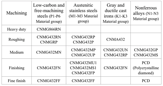
Figure 5 showcases examples of Kennametal’s negative and positive inserts, illustrating their application in machining operations.
Common Chip Breaker Configurations
Kennametal employs the following abbreviations to represent chip breaker geometries for various machining needs:
- F – Sharp
- FF – Fine Finishing
- FN – Finishing Negative
- MN – Medium Negative
- RN – Roughing Negative
- RW – Roughing Wiper
- UF – Ultra-Fine Finishing
- LF – Light Finishing
- MF – Medium Finishing
- RH – Roughing Heavy
- FW – Finishing Wiper
- UP – Universal Positive
- HP – High Positive
- K – Light-Feed Chip Control
This classification system allows machinists to select the most suitable chip breaker geometry for their unique machining needs, striking the perfect balance between performance, tool durability, and surface quality.
Figure 6: Kennametal Inc. Chip Breaker Identification System. Courtesy of Kennametal Inc.
Figure 6 highlights Kennametal’s chip breaker identification system, providing clear guidance on selecting the appropriate geometry for specific cutting conditions.
This system helps machinists achieve their goals by:
- Balancing Performance and Tool Life: Ensuring the chip breaker matches the application to reduce tool wear.
- Enhancing Surface Finish: Improving machining outcomes by minimizing tool marks and optimizing chip control.
- Customizing for Materials: Tailoring chip breaker configurations to the workpiece material for maximum efficiency.
Indexable Insert Identification Decoder
To simplify insert selection, this decoder tool helps machinists decode the characteristics of indexable inserts based on the ANSI B212.4-2002 standard. Input the codes to reveal specific insert attributes.
This tool enhances productivity by simplifying the selection process, ensuring machinists always choose the correct insert for their needs.
Kennametal Indexable Inserts
Selecting the right indexable insert is critical for achieving optimal performance. Kennametal provides a wide range of inserts tailored to specific materials, cutting conditions, and machining requirements.
One commonly used indexable insert for general turning is the CNMG 432, known for its versatility and reliability in a range of applications.
Due to the magazine’s space limitations, the authors provide the following tables showing the most popular Kennametal indexable inserts for general turning of steel, cast iron, and nonferrous alloys. These tables don’t cover all Kennametal chip breakers. (Figure 4 and Figure 6 also show Kennametal Inc. insert identification system and chip breaker identification system, respectively.)
Table 1: Negative indexable inserts. Image courtesy of Edmund Isakov.
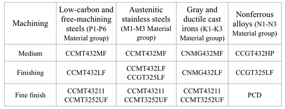
Table 2: Positive indexable inserts. Image courtesy of Edmund Isakov.
About the Authors
Edmund Isakov, Ph.D.: Consultant and author of books on metal cutting. Contact: edmundisakov9701@comcast.net
Shi 'Steve' Chen: Manager of Product Engineering at Kennametal. Contact: Shi.Chen@Kennametal.com
Closing Remarks
The ANSI B212.4-2002 standard serves as a foundational guide for identifying and selecting indexable inserts, empowering machinists to achieve precision and efficiency in their operations. Combined with Kennametal’s advanced chip breaker system and extensive range of inserts, this comprehensive guide simplifies complex decision-making, ensuring machinists select the best tools for their specific applications.
Whether you’re optimizing for surface finish, tool longevity, or chip control, the information provided in this guide will help streamline your machining process, reduce downtime, and enhance overall productivity.
Related Glossary Terms
- abrasive
abrasive
Substance used for grinding, honing, lapping, superfinishing and polishing. Examples include garnet, emery, corundum, silicon carbide, cubic boron nitride and diamond in various grit sizes.
- alloys
alloys
Substances having metallic properties and being composed of two or more chemical elements of which at least one is a metal.
- boring
boring
Enlarging a hole that already has been drilled or cored. Generally, it is an operation of truing the previously drilled hole with a single-point, lathe-type tool. Boring is essentially internal turning, in that usually a single-point cutting tool forms the internal shape. Some tools are available with two cutting edges to balance cutting forces.
- chamfering
chamfering
Machining a bevel on a workpiece or tool; improves a tool’s entrance into the cut.
- clearance
clearance
Space provided behind a tool’s land or relief to prevent rubbing and subsequent premature deterioration of the tool. See land; relief.
- countersink
countersink
Tool that cuts a sloped depression at the top of a hole to permit a screw head or other object to rest flush with the surface of the workpiece.
- edge preparation
edge preparation
Conditioning of the cutting edge, such as a honing or chamfering, to make it stronger and less susceptible to chipping. A chamfer is a bevel on the tool’s cutting edge; the angle is measured from the cutting face downward and generally varies from 25° to 45°. Honing is the process of rounding or blunting the cutting edge with abrasives, either manually or mechanically.
- gang cutting ( milling)
gang cutting ( milling)
Machining with several cutters mounted on a single arbor, generally for simultaneous cutting.
- indexable insert
indexable insert
Replaceable tool that clamps into a tool body, drill, mill or other cutter body designed to accommodate inserts. Most inserts are made of cemented carbide. Often they are coated with a hard material. Other insert materials are ceramic, cermet, polycrystalline cubic boron nitride and polycrystalline diamond. The insert is used until dull, then indexed, or turned, to expose a fresh cutting edge. When the entire insert is dull, it is usually discarded. Some inserts can be resharpened.
- inscribed circle ( IC)
inscribed circle ( IC)
Imaginary circle that touches all sides of an insert. Used to establish size. Measurements are in fractions of an inch and describe the diameter of the circle.
- milling
milling
Machining operation in which metal or other material is removed by applying power to a rotating cutter. In vertical milling, the cutting tool is mounted vertically on the spindle. In horizontal milling, the cutting tool is mounted horizontally, either directly on the spindle or on an arbor. Horizontal milling is further broken down into conventional milling, where the cutter rotates opposite the direction of feed, or “up” into the workpiece; and climb milling, where the cutter rotates in the direction of feed, or “down” into the workpiece. Milling operations include plane or surface milling, endmilling, facemilling, angle milling, form milling and profiling.
- precision machining ( precision measurement)
precision machining ( precision measurement)
Machining and measuring to exacting standards. Four basic considerations are: dimensions, or geometrical characteristics such as lengths, angles and diameters of which the sizes are numerically specified; limits, or the maximum and minimum sizes permissible for a specified dimension; tolerances, or the total permissible variations in size; and allowances, or the prescribed differences in dimensions between mating parts.
- rake
rake
Angle of inclination between the face of the cutting tool and the workpiece. If the face of the tool lies in a plane through the axis of the workpiece, the tool is said to have a neutral, or zero, rake. If the inclination of the tool face makes the cutting edge more acute than when the rake angle is zero, the rake is positive. If the inclination of the tool face makes the cutting edge less acute or more blunt than when the rake angle is zero, the rake is negative.
- relief
relief
Space provided behind the cutting edges to prevent rubbing. Sometimes called primary relief. Secondary relief provides additional space behind primary relief. Relief on end teeth is axial relief; relief on side teeth is peripheral relief.
- tolerance
tolerance
Minimum and maximum amount a workpiece dimension is allowed to vary from a set standard and still be acceptable.
- toolholder
toolholder
Secures a cutting tool during a machining operation. Basic types include block, cartridge, chuck, collet, fixed, modular, quick-change and rotating.
- turning
turning
Workpiece is held in a chuck, mounted on a face plate or secured between centers and rotated while a cutting tool, normally a single-point tool, is fed into it along its periphery or across its end or face. Takes the form of straight turning (cutting along the periphery of the workpiece); taper turning (creating a taper); step turning (turning different-size diameters on the same work); chamfering (beveling an edge or shoulder); facing (cutting on an end); turning threads (usually external but can be internal); roughing (high-volume metal removal); and finishing (final light cuts). Performed on lathes, turning centers, chucking machines, automatic screw machines and similar machines.