Rotary Dressing: Stop Whining
Rotary Dressing: Stop Whining
The Grinding Doc takes on anti-directional dressing.
Dear Doc: I attended your class and know you're a strong believer in using a +0.8 unidirectional speed ratio during rotary dressing. However, some of our shop-floor people still insist on dressing anti-directional. How can I convince them?
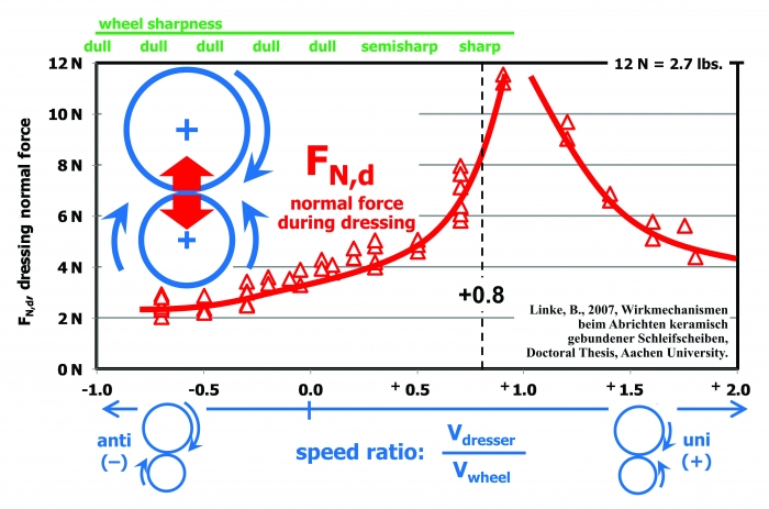
The Doc Replies: First, the speed ratio is the surface velocity of the dressing roll divided by the surface velocity of the grinding wheel. (That's surface velocity, not rpm.) Anti-directional uses a negative sign (see the figure), and unidirectional uses a positive sign. For example, if your dressing roll is going 12,000 sfm in the clockwise direction and your grinding wheel is going 16,000 sfm in the counterclockwise direction, your speed ratio is +0.75. I strongly recommend being in the ballpark of +0.8, especially for those working in the aerospace industry, where grinding burn must be avoided at all costs. This will provide a sharp-dressed grinding wheel.

Typically, people still like to dress anti-directional for two reasons.
First, anti-directional will impart a finer surface finish because all those dull-dressed grits polish the workpiece. If the grit size in the wheel is too large, operators have no choice but to dress the wheel dull by going anti-directional. Unfortunately, this creates a lot more grinding heat. Here, switch to a finer-grit wheel and go unidirectional. I've eliminated lots of grinding burn this way.
Second, anti-directional will exert a smaller normal force during dressing. If your dressing spindle isn't stiff or you have a wide dressing roll or disc, you will get more deflection of the wheel spindle and the dressing spindle. Even worse, you'll have a bigger risk of chatter during dressing. In other words, the dressing spindle starts vibrating uncontrollably. When this happens, you'll hear the dresser moaning, whining and screaming in protest. Operators then switch to anti-directional, and the moaning disappears—but the grinding burn begins.
The figure shows the measured normal force acting on the dressing spindle during dressing, based on the speed ratio. As we get closer and closer to Vdresser/Vwheel = +1.0, the dressing forces increase drastically. This causes the vibration and moaning.
But I don't want you to dress anti-directionally, because that creates a dull wheel, which causes grinding burn, grinding chatter, excessive part deflection and longer cycle times when grinders start slowing down feed rates to cope.
So what's the solution? It's usually a trade-off. Dress with a +0.4 ratio. Your wheel won't be quite as sharp, but your dressing forces will be cut in half—and hopefully the screaming will go away.
If you're using a traverse disc, switch to a thinner disc. That will also reduce the normal force.
Also, some operators use anti-directional because they can dress in a new wheel more quickly. Imagine taking 1.0" off the diameter of a new wheel to put in a form. That dress-in takes a long time. Switching from Vdresser/Vwheel = +0.8 to Vdresser/Vwheel = -1.0 will cut your forces by a factor of four, meaning you can dress at four times the feed rate.
But this will give you a dull wheel. The solution? Dress in the wheel at -1.0, leave 0.004", and then dress in that last 0.004" with a +0.8 ratio. You'll be able to dress superfast and also get a sharp wheel for grinding. The best of both worlds. Try it.


