Testing: The ups and downs of wheel performance when creep-feed grinding
Testing: The ups and downs of wheel performance when grinding wheel is slowly fed into the workpiece at sufficient depth of cut to accomplish in one pass what otherwise would require repeated passes. S…" title="Grinding operation in which the grinding wheel is slowly fed into the workpiece at sufficient depth of cut to accomplish in one pass what otherwise would require repeated passes. S…" aria-label="Glossary: creep-feed grinding">creep-feed grinding
Results from testing aluminum-oxide vitrified-bond wheels and diamond wheels in three different bond systems show the proper diamond roll dresser design, application methods and wheel specification can help manufacturing engineers achieve optimal results from continuous-dress, creep-feed (CDCF) grinding.
Results from testing aluminum-oxide vitrified-bond wheels and diamond wheels in three different bond systems show the proper diamond roll dresser design, application methods and wheel specification can help manufacturing engineers achieve optimal results from grinding wheel is slowly fed into the workpiece at sufficient depth of cut to accomplish in one pass what otherwise would require repeated passes. S…" title="Grinding operation in which the grinding wheel is slowly fed into the workpiece at sufficient depth of cut to accomplish in one pass what otherwise would require repeated passes. S…" aria-label="Glossary: creep-feed grinding">creep-feed grinding.
The tests focused on three main areas: up vs. down grinding, creep-feed grinding and the choice of bonded diamond wheels or electroplated diamond wheels when grinding tungsten carbide.
All images courtesy of Norton/Saint Gobain
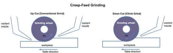
Figure 1. Up grinding (conventional) hardened steel with an aluminum-oxide wheel increases power draw and normal grinding forces and improves G-ratios, but imparts poorer surface finishes compared to down grinding. At right, down grinding (climb) tungsten carbide with a diamond wheel reduces normal grinding forces and tends to avoid workpiece edge chipping and thermal damage.
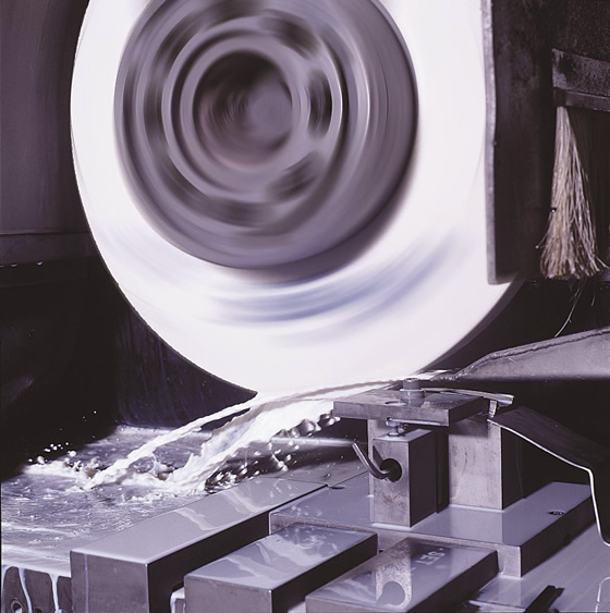
Norton/Saint-Gobain conducted all tests on a Blohm Profimat 410 106-hp creep-feed grinder. The feed rates were 2.5, 5.0, 7.5 and 10 ipm (63.5, 127, 190.5 and 254 mm/min.) when testing Al2O3 and diamond wheels. Each pass removed 1.0 cu. in. of 4340 steel hardened to 50 HRC at each feed rate. This was done twice, and the results were averaged. Presented here are some of the results.
A coolant nozzle delivered heavy-duty water-soluble oil at 5 percent concentration in typical city water to the wheel/workpiece interface. Coolant velocity matched the grinding wheel's peripheral velocity to assure penetration into the grinding zone. In addition, an overhead scrubber nozzle delivered coolant at 200 psi to the dress roll/wheel interface, cleaning the wheel during grinding.
Conventional or Climb?
Two tests evaluated the effects of up (conventional) and down (climb) creep-feed grinding (Figure 1). One was for Al2O3 wheels grinding 50-HRC 4340 steel and the other was for diamond wheels grinding C-2-grade tungsten carbide. Test results indicated up grinding hardened steel with Al2O3 wheels increased the power draw 6 percent and normal grinding forces 5 percent and imparted a 10 percent poorer surface finish, on average, compared to down grinding at heavy DOCs or high metal-removal rates of 0.3 cu. in./min. per inch of wheel width or greater. Up grinding improved the surface finish at a low mrrʹ (ʹ is prime) of 0.3 cu. in./min., in. or less or a DOC of 0.005 " (0.127mm) or less per pass.
When up grinding hardened steel with Al2O3 wheels, dynamometer measurements showed tangential forces were 42 percent higher compared to down grinding. This is possibly a function of coolant application. Up grinding requires two coolant nozzles, with one pushing coolant in the direction of the resultant tangential force, possibly explaining the dramatic increase seen on the dynamometer.
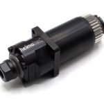
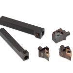
Figure 2. Ground RPC roll compared to unground RPC roll.
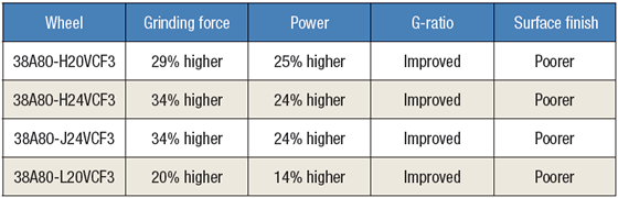
Using ground or lapped diamond rolls to dress vitrified wheels when continuous-dress, creep-feed grinding offers no net advantage compared to unground diamond rolls. Ground rolls create higher grinding forces and improve the G-ratios, but degrade surface finishes.
When creep-feed grinding tungsten carbide with diamond wheels, the down-cut mode exerts relatively low grinding forces, lowering the power draw 26 percent, and tends to avoid workpiece surface-edge chipping and thermal damage. In addition, coolant application was more difficult when up grinding. Tungsten carbide, as well as ceramic, chips form via pulverization with a significantly lower coefficient of friction compared to grinding steel, which produces ductile, curly chips. Also, the normal grinding forces are higher for steel alloys.
Normal grinding forces generated in the up-cut mode when creep-feed grinding tungsten carbide with an electroplated-bond diamond wheel were 16 percent higher compared to down grinding. Half of this increase comes from the wheel being dull because the down-cutting test was conducted before the up-cutting test. Although wheel dullness contributed, the difference in power draw between up and down grinding was substantial at about 22 percent. The interrupted cut and part geometry, such as corner radius and surface finish, likely contributed to this effect. The relative change in grinding power was the same for both techniques, indicating the force from coolant application had little impact on the results.
Consistent with the increase in grinding forces, up grinding improved surface finishes by 16 percent. This is because the rubbing and plowing portion of chip formation occurs at the part surface when up grinding, whereas that portion of chip formation occurs in the area of the part where the stock is already removed during down grinding. Up grinding, therefore, tends to burnish the surface at a low mrrʹ, improving the finish. The difference is more apparent in deep-cut creep-feed grinding than "line" contact grinding.
Diamond Roll Design
Two tests evaluated diamond dresser roll design and its impact on creep-feed grinding performance. One test evaluated the effects of roll type and diamond concentration: reverse-plated, high-diamond concentration vs. metal-bond, low-diamond concentration. The second test revealed the results of dressing with ground or lapped rolls and unground or unlapped reverse-plated diamond rolls. Test results indicated:
1. Using Al2O3 vitrified-bond grinding wheels dressed with reverse-plated diamond rolls lowered the specific grinding power 10 percent and grinding forces 18 percent, provided equal G-ratios (ratio of the volume of ground material removed from the workpiece to the volume of material removed from the grinding wheel) and imparted 36 percent poorer surface finishes compared to cemented diamond particle (CDP) dresser rolls. Also, the test showed an increase in diamond concentration results in a more aggressive, or sharper, grinding action.
2. It's not recommended to dress a vitrified wheel with a ground, or lapped, diamond dresser roll because it will increase grinding forces, which can result in a wheel acting two to three grades harder after dressing. This improves the G-ratio but imparts a poorer surface finish. The only reason to dress with this type of roll would be when it's the only way to correctly form the diamond or use reinforcement stones to hold form.
When dressing with the reverse-plated-construction (RPC) roll, which had a high diamond concentration, the grinding wheel was more open and sharper cutting compared to dressing with a CDP roll, which had a low diamond concentration. Normal grinding forces were 18 percent lower and the power consumption was 10 percent lower when dressing with the RPC roll compared to the metal-bond roll. G-ratios were unaffected but the surface finishes were 36 percent poorer after dressing with the RPC roll because of the sharper grinding action.
Test results showed roll type had little impact on the wheel's ability to hold form as a function of power draw. Wheel wear rates from using RPC dresser rolls revealed that the wheel acted as if it were a substantially softer grade. These results indicated the lower diamond concentration increased grinding forces but improved surface finishes.

Figure 3. A continuous-dress, creep-feed grinding test on a nickel-base alloy shows the surface finish becomes rougher when the wheel speed decreases because lower speeds create thicker chips, which directly correlates to a poorer surface finishes.
Parameters for test in Figure 3: +0.8 speed ratio; 0.000020-ipr compensation; mrrʹ = 0.450 × in.3/min., in.; Table speed = 14 ipm; DOC = 0.032"; Down cut (climb).
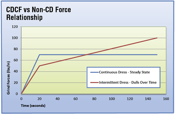
Figure 4. The difference in relative grinding forces in continuous-dress and intermittent-dress creep-feed grinding vs. time using aluminum-oxide grinding wheels.
RPC dresser rolls exhibited less roller wear compared to metal-bond dress rolls. The RPC design is durable and able to maintain tight tolerances and part geometry because of the high concentration of small, tightly packed diamonds. This gives the dresser rolls more cutting edges, making them more aggressive and more accurate.
Using two different RPC 30- and 40-mesh diamond dresser rolls, four different creep-feed grinding specifications were tested. One roll was completely ground or lapped and the other roll was not. This test revealed a substantial difference in grinding performance for wheels dressed with ground RPC rolls compared to wheels dressed with unground RPC rolls.
A 38A80-H24VCF3 wheel dressed with a ground diamond roll gave a 34 percent increase in normal grinding force per unit mrrʹ and a 24 percent increase in power draw. Although the workpiece was burn free when ground at a 7.5-ipm feed rate after dressing the wheel with the unground roll, the workpiece readily burned at the same feed after dressing the wheel with the ground roll. This is because the ground roll dulled the wheel and made it act two to three grades harder compared to the wheel dressed with the unground diamond roll. The G-ratio always improved when using the ground roll but the surface finish always diminished because of excessively high grinding forces (please see Figure 2 above).
These tests showed no advantage to applying ground or lapped rolls to dress vitrified grinding wheels. When seeking a harder grinding action, use a harder wheel specification. This harder specification will yield finer surface finishes and higher grinding forces.
Tuning an Application
Optimizing a CDCF application requires fine tuning four elements: wheel specification, wheel speed, dressing parameters and mrr. The workpiece material and geometry play an integral part in choosing the parameters. Another important point is that lower wheel speeds impart poorer surface finishes.
A CDCF test was conducted on an aerospace-grade, nickel-base alloy (Figure 3). The wheel specification was 38A80-E20VCF3. The grinding speeds tested were 6,000, 5,500 and 4,500 sfm. The surface finish values ranged from 35 µin. Ra at 6,000 sfm to 41 µin. Ra at 4,500 sfm. This is consistent with conventional thinking because lower grinding speeds produce thicker chips, which results in rougher surface finishes.
CDCF grinding controls the sharpness of the grinding wheel, allowing for higher mrr without metallurgical damage to the workpiece. By controlling wheel sharpness, a steady-state condition results where sharpness is controlled by simultaneously dressing the wheel while grinding. Intermittent dressing starts with a sharp wheel, but it dulls with use, increasing the grinding forces until wheel failure occurs. Hence, CDCF grinding with a harder wheel specification at a higher mrr enhances control but lowers the G-ratio while consuming more abrasive.
When CDCF grinding, the G-ratio could increase significantly compared to intermittent dressing, but this is offset by increased productivity and improved surface quality on difficult-to-grind materials. Because of the difficulty of grinding nickel-base alloys, CDCF grinding with Al2O3 vitrified wheels provides critical benefits when producing high-quality jet turbine components (Figure 4 above).
Grinding Tungsten Carbide
Another test involved creep-feed grinding C-2-grade tungsten carbide with various diamond wheels on the Blohm Profimat grinder. The wheels measured 14 "×0.450 "×5 " (355.6mm × 11.4mm × 127mm), and wheel variations included grit size, grade and bond system. Forty parts were ground at each of three mrr per truing and dressing operation. Each part was ¼ " (6.35mm) long with a ¼ " space between parts to create an interrupted cut, modeling the field-application condition. The slots were 0.450 " wide, and the DOC was 0.040 " (1.02mm) per pass. The plated wheels were trued to 0.0002 " (0.0051mm) maximum with an indicator. Stick dressing was not performed. The bonded wheels were trued with a brake-controlled truing device and stick dressed at a 5-ipm plunge into the wheel face, using a soft Al2O3 stick with a finer grit than the wheels.
Test results showed the plated diamond wheels consistently became dull with use, making their performance difficult to predict and control. Grinding forces constantly rose and surface finishes improved with use. A trued and dressed wheel, with its multiple abrasive layers, always per-forms better because a new abrasive layer is exposed.
Grit size had the most impact when creep-feed grinding tungsten carbide. All diamond wheels tested imparted a fine surface finish in relation to their grit size. In general, bonded diamond wheels generate finer surface finishes, hold form better and provide more consistent grinding forces than electroplated diamond wheels.
The test results for the electroplated wheels in the three grit sizes showed distinct differences in G-ratios and surface finishes; however, the difference was not apparent for grinding forces because of an inherent, constant dulling effect with electroplated wheels.
Vitrified-bond diamond wheels drew more power than resin-bond and electroplated wheels. The ASD320-R100B59 resin-bond wheel held form better than all others, with the SD320-J100VCF vitrified wheel coming in a close second. The PD320 electroplated wheel produced the best overall results until it significantly dulled at a rate of about 20 percent faster than 180-grit wheels. The SD320-J100VCF was best at the higher mrr, and the ASD320-R100B was best when forces were low.
The resin-bond system drew less power than all other bond systems for 180-grit wheels. This specification also generated slightly improved surface finishes. The resin-bond wheel, however, was more difficult to true than the vitrified (K100VCF) wheels. The electroplated wheel had the best G-ratios because of its dulling and high grinding force behavior. The BX resin-bond wheel held corners better than the 180-grit vitrified and plated wheels. The BX resin wheel also showed the most consistent wheel wear rates, but the SD180-K100VCF vitrified wheel showed improved wear rates, indicating a harder grinding action.
The plated wheels dulled rapidly, indicating coarser grit sizes would improve wheel life. Finer grit sizes resulted in higher grinding forces and substantially finer surface finishes. However, a coarse-grit wheel is more difficult to true than one with a fine grit.
Understanding the grinding forces and how they impact the grinding process is key to making proper parameters adjustments for process optimization. Effects due to changes in wheel speed, direction of the feed rate and dressing conditions must be optimized for the application and grinding machine. Surface finish, geometry, metallurgical interactions and system stiffness all govern the application and the systems approach for it. CTE