Vibration de-escalation
Vibration de-escalation
New and traditional part grinding technologies combine to control vibration and improve precision.
Historically, grinding has generated the tightest tolerances and finest surface finishes compared to other metalworking processes. Advances in materials and components for part grinders and machine design are helping to preserve that advantage.

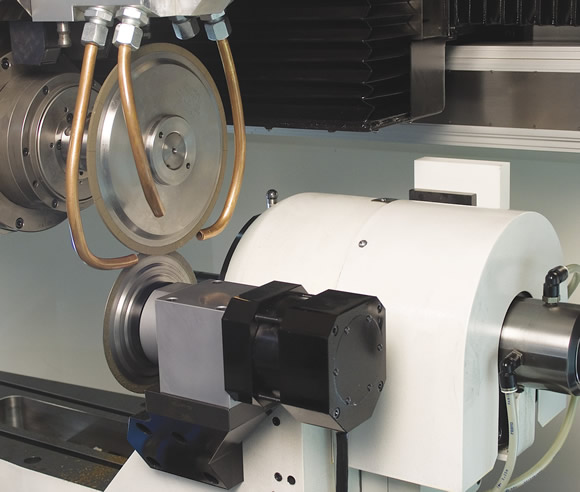
Courtesy of Marposs
An acoustic emission measurement system from Marposs.
Builders and users of multitask machines, for example, are adding grinding heads to live spindles for in-process operations. Also, many tooling components and microparts are produced exclusively via grinding.
With the need for tighter tolerances and smaller ground parts, grinding success depends more than ever on minimizing vibration at the grinding wheel/workpiece interface. Problems caused by vibration include chatter, poor surface finish and excessive wheel wear. Depending on the workpiece, application and shop environment, vibration damping—or prevention—can take many forms.
Spindle Selection
"Machine tool spindles are just one of many variables that determine the surface finish," said Gary Quirion, president of GMN USA LLC, Farmington, Conn., which builds and services high-speed spindles. "A poorly designed or worn spindle with elevated vibration levels will produce less than optimal surface finishes, so selecting the right spindle is crucial." Spindle designs with appropriate rigidity, stiffness, power and speed for specific grinding applications are key, he added.
In some applications, a spindle must have special features and dimensions. For example, deep-hole grinding may require a spindle with a small diameter relative to its length. Special care must be taken to ensure that spindles like this have maximum stiffness and rigidity to reduce potential frequency-generating issues.
Other vibration-limiting factors include selecting the wheel composition and speeds and feeds appropriate for the workpiece. Poor surface finish may result from vibration caused by part imbalance from improper workholding, an often-overlooked factor, according to Quirion. Other vibration sources include spindle drive issues; incorrect motor parameter settings for high-frequency, motorized spindles; and pulley, drive belt or drive motor issues with belt-driven spindles.
Balancing the Equation
Most ID grinding applications have spindle size limitations that preclude the use of a wheel balancing device. Lowering feeds and speeds to overcome inadequacies in the spindle or tooling design can reduce vibration and improve surface finish, albeit at slower production rates.
For OD applications, the same factors should still be considered, according to Quirion. "However, OD grinding applications typically require larger spindle designs, which would allow wheel balancers to be used. These balancers typically are internally mounted in the spindle shaft, externally mounted on the shaft or mounted in the wheel hub assembly."
Wheel balancing can be performed manually or automatically using systems with a series of movable weights in the wheel flange, or cup. In manual units, a sensing unit detects and defines the imbalance and instructs the operator where to place the weights. Automatic balancing uses similar sensing equipment to actuate and place motorized balancing weights.
Courtesy of United Grinding
A dressing operation on the Walter Helitronic Vision grinder.
Wheel balancing systems are typically built into grinding spindles, but can be retrofitted to existing units. Hydraulic balancing systems use coolant or oil instead of weights. Balancing normally occurs before grinding and after intermittent wheel dressing.
Dave Hayes, president of gaging equipment manufacturer Control Gaging Inc., Ann Arbor, Mich., is enthusiastic about in-process measuring and dynamic wheel balancing. These systems should cover a range of wheel sizes, compositions and machine types and be easy to install, he said. Looking into the future of wheel balancing, Hayes sees improvements in intelligent process control and the addition of more sensors to the balancer, making it more effective.
"Traditionally, we have been able to detect tool (wheel) wear through adaptive control systems," he said. "We're very close to the point at which we'll be able to compensate for it in real time."
Hans Ueltschi, vice president of cylindrical sales for grinding machine builder United Grinding Technologies Inc., Miamisburg, Ohio, cautioned that sensor-based systems are not foolproof. "Although sensors within balancing systems and gap elimination systems are constantly improving, the operator still must set dressing intervals within a tolerance band based on the material, wheel composition and wheel speed," he said.
In production environments, especially ones involving large-diameter wheels, hydraulic balancing is common, added Markus Stolmar, vice president of sales for United Grinding's tool grinder division in Fredericksburg, Va. The technique involves the controlled injection of coolant or oil into a series of chambers in a balancing container or into the wheel flange itself to create the proper equilibrium.
In smaller-diameter wheel applications, offline dressing is common. For multiple-grinding-machine operations that use small-diameter wheels, the use of centralized, off-machine wheel management systems has been gaining in popularity because of their improved efficiency, according to Stolmar. Composed of a balancing unit, a wheel dresser and a CNC laser-based measuring machine, the system is typically used to balance the wheel, dress it, balance it a second time and then measure wheel geometry. Because of the high cost in terms of components and manpower, off-machine systems are typically reserved for large, multiple-machine grinding operations.
Frank Powell, product manager, grinder products, for Marposs Corp., Auburn Hills, Mich., a manufacturer of measurement and control equipment, agreed that balancing is a key tool to control vibration. "In any precision application, close attention to balancing is essential," he said. "Grinding wheels vary in their composition and, after every dressing, it is necessary to inspect and rebalance the wheel."
Listen and Adapt
Another technique that can mitigate vibration problems is acoustic sensing, according to Powell. Acoustic systems have been available since about 1984 and have become more popular as the quality of CBN wheels has improved. "[CBN wheels] virtually require acoustic sensing," he said. "This is due to the speeds at which they are typically run and the need to detect problems as soon as possible."
Acoustic sensing focuses on the triad of material, wheel and machine. Once the "normal" acoustic profile of the grinding system is established and recorded, any deviant variation registers immediately. Corrective action, usually involving wheel dressing and rebalancing, can then be taken.
While useful, acoustic control can be challenged by new work materials. "For example, the individual components of multiple-layer, composite materials have different characteristics," Powell said. "The movement from one layer to another when grinding can create an entirely different acoustical profile and throw the system off. Tighter control may be required for those applications."
Another vibration control tool is the grinding wheel adapter. As CNC machines equipped with tool magazines have become more prevalent, the grinding wheel adapter plays an increasingly significant role, according to John Manley, president of Machine Tool Systems Inc., a Toronto-based supplier of CNC grinders and abrasive products. "A compression-fit wheel adapter is best for precision grinding applications." The adapter fits and locks the grinding wheel to the toolholder. The tight fit eliminates vibration between the wheel and the holder.
Micropart Imperative
Demand for microparts is growing from industries as diverse as medical, aerospace and energy. As new materials, including advanced ceramics and composites, are used to make microparts, abrasive machining will play an increasingly important role, according to Ed Sinkora, senior product manager for United Grinding's tool grinder division. The techniques involved owe much to cutting tool grinding technology, he said. Controlling vibration when grinding micro parts and features is even more important than when grinding larger parts because their small size makes them more susceptible to distortion.
Sinkora said: "The need for high wheel speeds is the greatest problem in dealing with vibration [when grinding microparts]. Anything that flexes the part will cause an unacceptable degree of distortion. Our challenge is two-fold: seek strategies that do not induce vibration and dampen any vibration that occurs. When it comes to small tools—or small parts—that becomes a real challenge."
Sinkora sees simulation as a big part of the answer to control vibration when making micro parts and tools. "To achieve the optimal process, our applications people and customers utilize real-time, 3-D simulation. By performing a volumetric analysis of the material removal for every operation, we can anticipate the timing of negative factors that can cause vibration, like excessive wheel load, and correct them—whether that involves changing feed rates, wheel dressing or changing wheels."
A Strong Foundation
United Grinding's Ueltschi said the machine base is still the biggest factor in preventing vibration when grinding parts of any size. "Our mineral cast bases, what we call Granitan, are literally three times better than cast iron in preventing vibration."
"Vibration dampening begins with the machine," agreed Machine Tool Systems' Manley. "Because vibration dampening and thermal stability are crucial, we recommend units constructed with a synthetic granite base."
A highly stable base can control vibration enough to allow for the use of conventional bearings in most cylindrical grinding applications. However, for imparting surface finishes as fine as 0.5µm Ra, hydrodynamic bearings are typically needed, Ueltschi noted.

Courtesy of United Grinding
A probe operation on a tool grinding machine. Some of the same techniques appropriate for controlling vibration when tool grinding apply to making microparts.

Courtesy of Control Gaging
An in-process grinding measurement instrument from Control Gaging.
Also, multiple grinding parameters—including coolant concentration and volume, temperature of the workpiece and coolant, wear and other factors—must be taken into account before the fact to prevent vibration. "Sometimes the best way to dampen vibration is to ensure that it does not occur in the first place," Ueltschi said.
Some of the most dramatic advances in grinding have occurred in profile and surface grinding, according to Ueltschi. New tool changing, workholding and 5-axis technologies have opened new horizons in complex part generation, automation and increased production. At the same time, this has created some of the greatest challenges for vibration damping and prevention due to a number of factors, including decreased machine stability because of multiple axes of motion, and, in certain cases, the use of a toolholder rather than a grinding spindle.
Proper workholding is a key to preventing vibration, agreed Kevin Leatherwood, vice president of sales at Vibro/Dynamics Corp., Broadview, Ill., a manufacturer of isolation mounting systems. Steady rests are essential for cylindrical parts, he noted, particularly those with high length-to-diameter ratios, such as elongated shafts, boring tools and specialty screws. These parts are especially susceptible to runout. Prismatic parts are traditionally secured by magnetic chucks for surface grinding, but as parts become more complex, they may require additional customized fixturing.
Workholding for making small parts and tools may require some creativity, according to Machine Tool Systems' Manley. "In the case of grinding very skinny cutting tools, there are crazy tricks of the trade," he said. "Operators sometimes stuff cutting tool flutes with plasticene to reduce vibration. Others use elastic bands on the OD."
Another vibration challenge emerges when grinding ceramic parts, according to Larry Marchand, vice president, profile group for United Grinding in Miamisburg. In conventional grinding operations, vibration transfers between the multiple metal parts of the machine, as well as the wheel, workpiece and fixture. When grinding ceramics, however, there is no natural dynamic frequency, and preventing vibration transfer from the machine to the part becomes more difficult because of the difference in the frequencies of the materials involved. This can also be amplified by variations in workpiece density.
One solution, available on Mägerle grinding machines from United Grinding, is to eliminate vibration in the machine tool itself so it cannot transfer to the part. This is accomplished using frictionless, preloaded hydrostatic wraparound guide ways, which break vibration transfer by eliminating metal-to-metal contact by introducing a film of oil between the guide ways to preclude vibration transfer.
Covering the Basics
While new vibration-damping technologies have contributed markedly to accuracy, it remains critical to implement standard practices as well.
For example, the grinder must be isolated from environmental vibration. "Depending on the levels of ambient vibration, elimination strategies range from using free-standing mounts on the machine to adding elastomers or springs at the base of the machine to using a foundation poured separate from the plant floor that can be isolated with an elastomer cushion or, if necessary, mounted on springs," said Vibro/Dynamics' Leatherwood. The chosen strategy depends on several factors, including the amount of vibration in the shop environment, design and construction of the grinding machine, workpiece material characteristics and finish tolerances.
Better vibration isolation for any machine tool via mounts or a well- isolated shop floor foundation will improve part quality. Good industrial engineering practice suggests that, prior to original placement, the grinding area should be located away from other operations, such as presses, that generate heavy vibration.
The quest to minimize vibration is perhaps best described in terms of an asymptotic curve—a line that always approaches but never quite meets its apparent intended resolution. As long as there is mechanical motion, and as long as the grinding wheel interacts with the workpiece, vibration will be a factor. It might also be considered ironic that grinding, among all the machining processes, achieves the tightest tolerances and finest surface finishes, but also requires the greatest degree of human judgment and involvement. CTE
Reinventing the wheel
While attention is being given to processes that affect the grinding machine and wheel balance, developments regarding wheel structure are also ongoing. Radiac Abrasives Inc., Salem, Ill., offers the Genis vitrified CBN wheel from parent company Tyrolit, equipped with a carbon-fiber core, which exhibits significant vibration-damping characteristics compared to the traditional steel core, according to the company.

Courtesy of Radiac Abrasives
The Tyrolit Genis vitrified CBN wheel has a carbon-fiber core, which exhibits significant vibration-damping characteristics.
Tests indicate that, compared to ones with steel cores, fiber-core wheels significantly reduce vibration and corresponding chatter. This, in turn, extends the dressing cycle, resulting in improved performance and longer wheel life. Initially used in automotive part manufacturing, fiber-core wheel diameters typically range from 12 " to 24 ", depending on the application.
One application involved a 12-lobe truck camshaft made of 53- to 58-HRC steel. The steel-core wheel ground 3.7 camshafts in 6 minutes with a dressing cycle of 54 lobes. The fiber-core wheel produced 6.5 camshafts in 4 minutes with a dressing cycle of 120 lobes, according to Radiac. Fiber-core wheels also weigh less than steel-core ones, which makes them easier to load and may reduce grinder power consumption.
—F. Burke
Contributors
Control Gaging Inc.
(734) 668-6750
www.controlgaging.com
GMN USA LLC
(800) 686-1679
www.gmnusa.com
Machine Tool Systems Inc.
(416) 254-6298
www.machinetoolsystems.com
Marposs Corp.
(248) 370-0404
www.marposs.com
Radiac Abrasives Inc.
(800) 851-1095
www.radiac.com
United Grinding Technologies Inc.
www.grinding.com
(937) 859-1975
Vibro/Dynamics Corp.
(800) 842-7668
www.vibrodynamics.com


