CAD/CAM software and specialty tools have manufacturer supercharged
CAD/CAM software and specialty tools have manufacturer supercharged
The late Jerry Magnuson is a legend in the hot rod racing and aftermarket industry. Extending his love of the sport beyond the track, Jerry and his wife, Maureen Magnuson, started Magnuson Products LLC, Ventura, California, after many years of designing and building supercharger kits for the aftermarket. The company also supports OEMs.
Article from CNC Software Inc.
The late Jerry Magnuson is a legend in the hot rod racing and aftermarket industry. Extending his love of the sport beyond the track, Jerry and his wife, Maureen Magnuson, started Magnuson Products LLC, Ventura, California, after many years of designing and building supercharger kits for the aftermarket. The company also supports OEMs.
Magnuson designed, engineered, machined and assembled over 32,000 superchargers for Toyota Racing Development (TRD) over a 16-year period of time and continue to build superchargers for many OEMs, such as Lotus, as they have for the last 12 years. Magnuson sold the company to Kim Pendergast in 2010. Both Jerry and Pendergast come from Mid-Western farm families. Maybe that's why he entrusted his business and legacy to her.
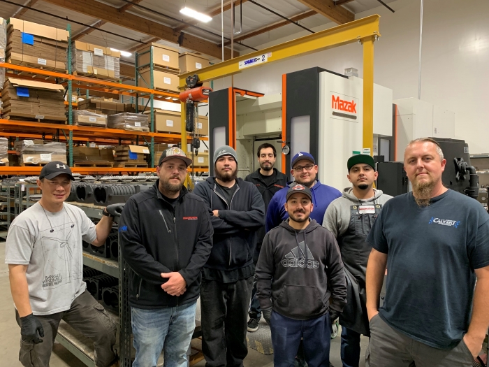
The machining team at Magnuson Superchargers (left to right): Manuel Casasola, William Barton, Miguel Vallin Manzanarez, Kenton Klucker, Erik Perez, Javier Felix, Jesse David and Hubert Gromek.
Superchargers are like air pumps that pump the air forced into the engine to create more horsepower. According to Hubert Gromek, machine shop manager at Magnuson, every little part of the superchargers, down to the most miniscule component, is important. That is why, after many years of outsourcing various machining processes, experiencing longer lead times and, at times, substandard quality, the shop invested in eight CNC mills and three lathes, and four seats of MastercamCAD/CAM software from CNC Software Inc., Tolland, Connecticut, to power the operation. Today, nine machinists help churn out roughly 3,000 to 4,000 parts per month; 80% to 90% of all products are produced in-house in two shifts per day. Gromek, who has been with Magnuson for more than 17 years, working from the ground up, eventually became the machine shop manager four years ago. He is the only full-time programmer but is training his shop supervisor in mill and lathe programming.
The finished TVS 2650 6061 aluminum billet supercharger lid and manifold shows two billet brackets in the front, which became full production parts.
Cast 328 and 356 aluminum comprise the majority of parts manufactured at Magnuson. Made of sand-casted aluminum, they range in size from small brackets to full housings for big upper and lower manifolds that can be as large as 22"x17". They are intricate in terms of port design, flanges that must be super flat and O-ring grooves in various iterations. It's the latter that posed Gromek one of his earliest challenges as a programmer and a machinist. Engineering, with whom Gromek works closely, started designing dovetail O-rings and he had a hard time finding a tool that could do the kinds of dovetails they needed. His tooling distributor suggested the Harvey Tool dovetail cutters from Harvey Performance Co., Rowley, Massachusetts.
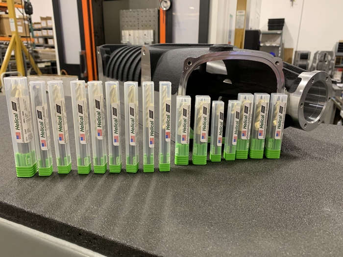
A selection of Helical endmills from Harvey Performance.
"The Dovetail O-ring is tricky. You have to rough out the slot with the smaller endmill. Some of these could be a nice short little O-ring or some can go around the entire sealing flange of a pretty decent size lid. The ones we mainly use are the 0.093" so it's a 3/32nds endmill – pretty small – and when we have to go all around the sealing flange of a supercharger system, the run times get pretty long when roughing these O-rings," said Gromek. He is now able to rough out material and then go back in with a dovetail tool to achieve a good finish and evacuate chips effectively. "I couldn't get the performances and finishes with the old tools. When my tool reps suggested these endmills it made a huge difference. Being able to speed everything up, I was able to double the feed rates and, with Mastercam, I can program where the entry hole is and where the exit hole is, which is more efficient."
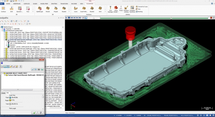
This 6061 aluminum billet supercharger manifold fits the TVS 2650 supercharger for Magnuson's Camaro racecar. Gromek used the Dynamic OptiRough toolpaths to remove the material quickly. After the roughing operation, he used 3D Surface Contour and the Pencil toolpath to help smooth the inside.
Gromek uses standard contour toolpaths to program the O-rings. He programs a circle helix bore toolpath for the entry hole; rather than plunging into the material and clogging up the tool, the helix bore "helixes" down to create the first starting hole. He then programs a standard contour toolpath to profile the circle toolpath.
"You can pick your start and end points," noted Gromek. "You can just click the center of the radius where you want to plunge the tool and it works well. I have many toolpaths to choose from."
Every type of supercharger has some sort of sealing flange, whether it's the front inlet that seals to the housings, requiring an air-tight seal, to the front of the housing where air enters the supercharger. Every one of these has an O-ring seal around it. Also to be considered is the supercharger itself, how it seals to the intake manifold and the O-ring groove around it that helps create a seal when it bolts to the lid. The lower manifold that seals to the heads on the engine also has an O-ring seal on the bottom that requires a perfect air-tight seal.
This pair of TVS 2650 drive covers were made from 6061 aluminum billet material. These parts are assembled with bearings and seals and a precision ground shaft that drives the supercharger.
"Almost every single part we do has some sort of O-ring groove. There are O-ring grooves that go all the way around a cover that can be as large as 20" x 15"," said Gromek. The right tools and software have saved Gromek considerable time.
The aforementioned sand castings also pose a challenge to the team. They are abrasive and take a toll on endmills. The Helical endmills feature proprietary Zplus coating that holds up to the rigors of machining these abrasive surfaces. "The porosity and abrasiveness of these castings eats up endmills pretty badly and the coating on the endmills seems to hold up very well. I'm getting a lot of tool life out of these. Plus the finishes come out amazing," said Gromek.
He pointed out that many shops do regrinds but, in his shop, it's better knowing that when his machinists grab an endmill out of their toolcrib, they know it will work with all of the feeds and speeds, and programs rather than taking chances and extra time reproving out programs. And, according to Gromek, it's all made a big difference with production times and part quality.
The self-taught programmer said he has evolved most with the software when programming the toolpaths for the company's master patterns and core boxes. They create the shape inside the large aluminum billets so the foundry can make the cores that go inside the castings. Surface finish is important so that the sand does not stick to the core box. The accuracy of the mold is critical. Gromek used to program a standard pocket routine which took a long time to rough the material out before programming standard toolpaths to finish the job.
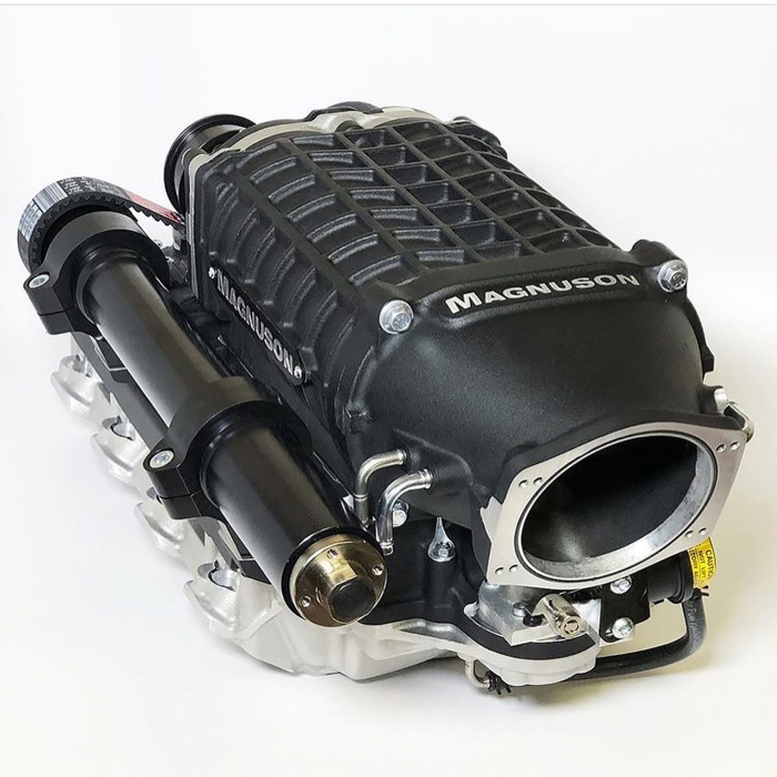
The TVS 2650 supercharger from Magnuson Products.
Sean Bellemeur, training manager at Mastercam Reseller CAD/CAM Consulting Services Inc., with locations in Newbury Park and Anaheim, California, showed him how to use Dynamic OptiRough toolpaths to save considerable time. Dynamic Motion, or Dynamic Milling, uses proprietary algorithms programmed into the software to keep the tool constantly engaged with the material, allowing it to cut intricate geometries at higher speeds. OptiRough toolpaths use Dynamic Motion but in a more precise way. The cut uses the entire flute length of the tool, but a small percentage of the tool's diameter on the first cut, followed by several successive shorter cuts that bring the part into the net shape desired.
"To be able to run at 200 to 300 inches per minute, almost 1" deep with a ½" endmill, just ripping through the material … something that used to take hours to hog out can take maybe an hour," reflected Gromek. "The finishes and quality of the part have improved."
Magnuson makes quite a few superchargers for many makes and models of cars and trucks, but the biggest of them all is the new TVS 2650, bigger in size due to the larger rotors, and bigger in scope due to all of the R&D work, flow testing, port development and consulting with race teams have helped take this supercharger to the next level. Magnuson's superchargers contain rotors made by Eaton's Performance Products Div., Cleveland. According to Gromek, they make the rotors and the bearing plates on the shafts while Magnuson makes the housings and the rest of the kit.
"We spent a year of testing on this product. The product that we released is the best product on the market in my opinion," said Gromek.
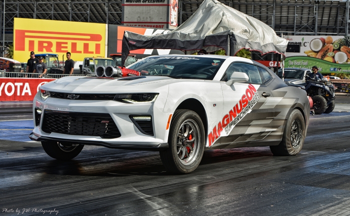
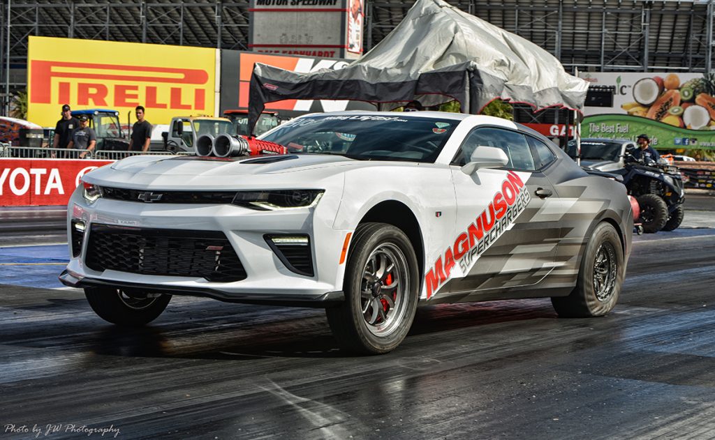
The Magnuson Camaro racecar.
Gromek said in the housing it's not a full diameter bore, more like a half moon shape on either side. It was a challenge figuring out how to program an interrupted cut going down the bores and being able to maintain that diameter with no taper, and ending it with a nice finish. "It took some trial and error because of the bigger diameter, and it is a little bit longer. I had to find tools and boring bars that are precise enough to hold that diameter, tolerance and depth tolerance, with no taper, and I had to come up with some new toolpaths to achieve it. We do it on our Mazak horizontal machining center, along with every other type of housing, because we needed the precision and accuracy of that machine to hold down the diameters of that size. Every single housing has O-ring grooves that use Harvey Tool #13993 miniature endmills to rough the groove and #23814 O-ring Dovetail tools to finish the groove."
Mastercam's tool library also helps shave time and ensure accuracy. "We run a lot of repeat jobs. Tool layout is roughly close. It's simple and quick to pull a tool out of the library with feeds and speeds already saved. Having the Harvey and Helical tools available makes it even better. It's literally the exact endmill I'm using," said Gromek.
Magnuson's success is due in no small part to its team. "I can't stress enough the importance of getting the right people in the shop, people who you can rely on to handle the tasks they are assigned with commitment and drive," explained Gromek. "Being a machinist is not an easy job. It took about four years to put together the right team. It fits us. The team and the team building experience are important."
To that end, the team assembled once a week for about 60 to 90 minutes to watch Haas "tip of the day" videos and Titans of CNC on YouTube to learn new and better techniques. A few machinists attended the five-day Mastercam mill and lathe programming classes at CAD/CAM Consulting.
This commitment to quality, paired with IATF16949 certification, has taken Magnuson into the direct OEM market. The company has joined the General Motors COPO Racing program, supplying the superchargers to GM factory production racecars.


