New tube-cutting technology for next-generation production needs
New tube-cutting technology for next-generation production needs
Stents and tubes are used in countless medical devices and new ones are being added every day, fueled in part by the growth of minimally invasive surgery and the commonplace use of stents. The sheer number and diversity of devices is rapidly increasing – and with it, the demand for more and more laser cut stents; flexible tubing, cannulas and micro cannulas, needles, biopsy devices and other minimally invasive tools.
By Geoff Shannon, Amada Miyachi America, and David Van de Wall, Amada Miyachi Europe
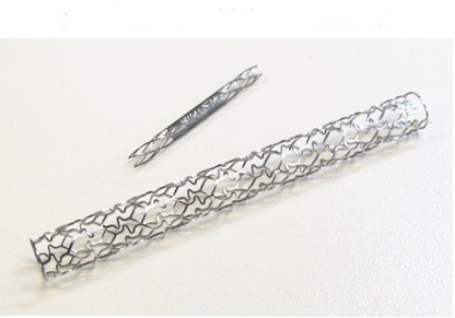
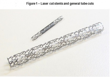
Stents and tubes are used in countless medical devices and new ones are being added every day, fueled in part by the growth of minimally invasive surgery and the commonplace use of stents. The sheer number and diversity of devices is rapidly increasing – and with it, the demand for more and more laser cut stents; flexible tubing, cannulas and micro cannulas, needles, biopsy devices and other minimally invasive tools. Figure 1 shows examples of common features in modern stents.
While legacy stent and tube cutting systems have performed well during recent decades, new cutting technologies coming onto the market offer faster and better cuts, with higher production rates and new and unique cutting capabilities.
Replacing legacy cutting systems
The pulsed neodymium-doped yttrium aluminum garnet (Nd:YAG) lasers used in the past 2 decades have definitely been great workhorses. They have performed well and been excellent manufacturing centers for many companies.
Unfortunately, the original integrated pulsed Nd:YAG lasers that remain in operation are now obsolete and difficult to service. While many of these systems have been upgraded to fiber lasers, they still have old stage sets that are a number of generations behind current technology. In addition, they are running on slow and aging controllers with legacy software.
Simply put, the laser, stages, controller, software, water systems and automated tube loader technology have all moved on. Here is a brief overview of improvements in these components that enable faster and better cuts with higher production rates and less downtime.
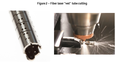
The pulsed Nd:YAG lasers used in the past have been superseded by fiber lasers with better beam quality that does not change with pulse energy and average power. This provides a smaller and more consistent focused spot size, which offers tighter cutting tolerances, and, with spot sizes down to 10 microns, the ability to cut much finer detail features. These lasers provide pulse frequencies up to and beyond 5 kilohertz (kHz) and pulse widths down to 20 microseconds (ms) to enable energy input optimization for a variety of tube materials and wall thicknesses. Higher frequencies can be implemented to maximize acceleration and speed for a range of part thicknesses. From an operational standpoint, the fiber lasers have a number of advantages. They are air-cooled, run off single-phase 240-volt electrical power and have diodes with lifetimes that are greater than 70,000 hours, which equates to minimal operational costs. Figure 2 shows an example of a tube produced by one of the new laser tube cutters on the market (left) and a close-up of laser tube cutting (right).
Fiber lasers use microsecond pulses and offer a cutting speed and edge quality that is sufficient for many applications. The femtosecond (fs) laser offers laser pulses that are under 400x10-15seconds (s), or about one million times shorter than the fiber laser. The very short pulse duration, combined with peak powers into the gigawatt level, offer a unique cutting capability. The fiber laser has a fusion cutting mechanism, whereby the laser pulse melts the metal, which is then ejected from the part by a coaxial high-pressure gas. The very high peak power of the fs laser and a pulse duration that is shorter than the material's conduction time creates a nearly pure vaporization mechanism. Because there is no melt creation during the cutting process, there is no burr, which is beneficial for such materials as nitinol.
Take the example of the ubiquitous coronary stent, one of the first devices manufactured with both Nd:YAG and fiber lasers. First, the part has to be machined, then honed, or cleaned out inside with a mechanical tool, and finally deburred. Then a chemical-etch process must be performed to clean up around the edges, followed by an electro-polishing step. These steps are quite time consuming. They can also cause the part to become brittle or deformed and may result in microcracks. Yields tend to be in the 70 percent range, which means the loss of a significant amount of end product, which is a significant material cost in the case of nitinol.
By contrast, the fs laser produces a burr-free cut that drastically reduces the number of time-consuming post processing steps; the part is machined and then undergoes an electro chemical process to round the edges. The integrity of the part is improved and yields can be closer to 95 percent. In addition, using a fs laser can be an attractive proposition for end users who may be looking to bring the cutting process in-house, but do not want to go through the arduous red tape exercise of also bringing in house the necessary chemical post-processing materials and processes needed for fiber laser cutting.
Table 1 shows an ROI comparison of a femtosecond laser and a fiber laser cutting a nitinol coronary stent.

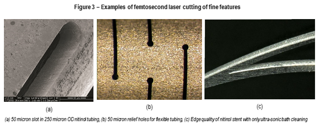
The fs laser with minimal heat input and exceptional heat input control is a very good tool for cutting small features in small parts with excellent edge quality and feature definition. Figure 3 shows some examples of fs laser cutting.
The majority of stents and tubing are metal. However, FDA-approved polymer stents and scaffolds are now on the market, which can only be cut with a femtosecond laser. The fiber laser does not absorb sufficiently well enough in the polymer to make quality cuts. The femtosecond laser has such great photon density that it is absorbed by the polymer material through a process known as multi photon absorption, which makes cutting possible. This cutting can be further enhanced by using a green wavelength over one micron, which provides better cut quality, faster speeds, and a larger processing window.
Software, controllers and stages
New digital motion controllers and improved stage accelerations enable users to follow the programmed tooling path with reduced following errors and faster accelerations and speeds, resulting in faster cycle times. In most tube cutting applications, the limiting factor for cycle time is the motion, specifically the rotary axes, and so stages and controller performance improvements are a key part of maximizing production.
As part of day-to-day operation, the interaction of the operator with the control software user interface can optimize efficiency in setup, process monitoring and reduce operator errors. The use of large screen monitors has facilitated single screen operator-orientated interfaces. Using the space on screen to organize areas of usage clearly, operators no longer have to battle the control software. Instead, they can become comfortable with it, and even use it to streamline processes for operational efficiency.
In addition, in-line sensors, gages, digital flow meters and valves can report on the status of all process-critical parameters, including assist gas pressure, water flow and pressure. Not only are these vital process conditions monitored, values can be set with alarms and error states for low levels to avoid wasted material stock, and, more importantly, equipment damage and downtime.
Water system
In many legacy system designs, the water system was a weak point, requiring constant attention and maintenance to keep the machine running. Such issues as small water tank sizes, short lifetime pumps and lack of internal flow monitoring, all added up to an unreliable system. Compounding these issues is the fact that it was difficult to access, even to simply change water filters. Fast forward to newer systems, which have a 10-gal. tank size, four-level debris filtering, intelligent programmable flow valves, multiple solenoid switches to prevent large water leaks and drawer-mounted hardware that enables filter changing in seconds. The user interface provides the operator all necessary information, along with pre-cutting safeguards and GO/NO-GO limits to ensure that all is well.
Automated tube loaders
The standard stent and tube cutter is loaded manually with tubing that is typically up to 3m long. The cutter then cuts parts and advances the tube according to the program. At some point, the amount of tube remaining is of insufficient length to make the cut, and the remainder is removed and a new tube loaded. With more pressure to improve productivity and minimize labor costs, many are now using automated tube loaders to feed the cutter tubes. While this is not new, there is now an increased potential for using these tube loaders for automated wet connect on tube diameters larger than 1.5mm. Although one should not operate the tube cutter in a totally "lights out" mode, using the automated loader can significantly reduce labor allocated to the machine.
Open-architecture system design
A key part of any system is making the hardware usable for the operator on an everyday basis. One feature that contributes to this is using composite over granite with better vibration damping. Because the composite has a uniform internal structure, it can be mechanically modeled and so optimized for vibration isolation, load bearing capacity and deflection under load. This enables a cantilever arm to support the focus optics and Z and cross axes stages, providing an open machine from an operator accessibility perspective.
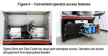
Figure 4 shows examples of convenient machine access, including equipment placed on pull-out drawers that makes changing water filters straightforward, along with any other necessary service items.
System design and cutting performance of the latest generation stent and tube cutting systems offer significant advantages and capability over legacy machines for increased productivity and enabling product innovation with better process capability. Whether using the fiber or femtosecond laser, improvements to motion, controller and control software make the latest stent and tube cutting system superior to legacy systems or provide new capability for future manufacturing needs.


