With hyperMILL 2014, OPEN MIND Technologies AG is announcing a range of brand-new innovative features in addition to improvements to existing functions. One of these new features is the "Deformation" module in the CAD part of the software, hyperCAD-S.
In hyperCAD-S, OPEN MIND has developed its own CAD system that is ideally matched to the CAM system hyperMILL. This CAM/CAD software is specifically designed to address the requirements of NC programmers. hyperCAD-S provides the hyperMILL CAM system with a modern and highly user-friendly interface.
The core of the CAD software has also been completely redeveloped. It has increased functionality in comparison with traditional CAD systems, which are customised for each individual CAD programmer. In version 2014, hyperCAD-S has been improved in a number of ways. One of the new features is the "Deformation" module, which opens up many new possibilities.
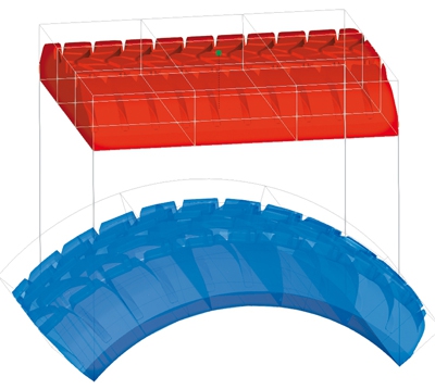
In hyperCAD-S, the user has the option to deform all geometries in accordance with requirements using the new "Deformation" module. This applies to both local and global component areas.
What is the benefit for CAM programmers? "It's quite simple," explains Konstantin Gambs, application engineer at OPEN MIND. "If warping occurs during the manufacture of thin-walled parts, for example, it is extremely useful to be able to compensate for this beforehand by making a specific change to the geometry."
This result is a part that meets the intended requirements. As an example, Gambs shows a turbine blade that has warped "a little" during production. All the CAM user needs to do is offset it in the opposite direction before generating the program. This will result in extremely accurate geometry after machining. Another example could be sheet metal tools. After stamping, sheet metal parts exhibit a springback effect that must be compensated for in advance to ensure that accurate sheet metal parts are produced. Another possible use is to apply existing 2D lettering to 3D geometries using volumetric deformation. In this process, selected elements (surfaces, curves, points, point clouds and meshes) are deformed volumetrically onto a target surface. There are no boundaries to user creativity.
Related Glossary Terms
- computer-aided design ( CAD)
computer-aided design ( CAD)
Product-design functions performed with the help of computers and special software.
- computer-aided manufacturing ( CAM)
computer-aided manufacturing ( CAM)
Use of computers to control machining and manufacturing processes.
- numerical control ( NC)
numerical control ( NC)
Any controlled equipment that allows an operator to program its movement by entering a series of coded numbers and symbols. See CNC, computer numerical control; DNC, direct numerical control.