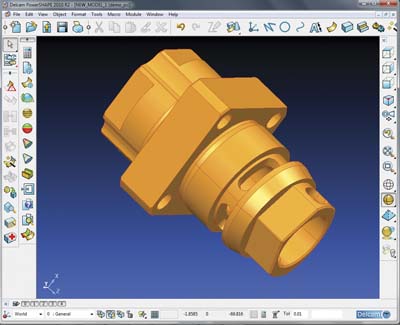
PowerSHAPE Companion for PartMaker
PowerSHAPE Companion for PartMaker
PartMaker Inc., a division of Delcam Plc, has introduced a new product called the PowerSHAPE Companion for PartMaker.

PartMaker Inc., a division of Delcam Plc, has introduced a new product called the PowerSHAPE Companion for PartMaker. It is based on Delcam's PowerSHAPE design software, which is already used at thousands of manufacturing facilities around the world alongside Delcam's PowerMILL CAM system for high-speed and five-axis machining.
This new 3-D CAD offering includes functionality for creating solid models, data repair, editing part designs for manufacture, and for the design of machining accessories, such as tool holders and machine components.
Like the PartMaker CAM suite, the PowerSHAPE Companion for PartMaker is based on the Parasolid Solid modeling kernel, assuring interoperability with both PartMaker and all other major CAD/CAM systems. The data repair functionality in the PowerSHAPE Companion for PartMaker includes PowerSHAPE's Solid Doctor. This allows users to read in and repair models from all sources, including standard formats like IGES and STEP, plus native files, such as CATIA, Siemens NX and Pro/Engineer, and output a file that can be read directly into PartMaker.
With the Solid Doctor, PartMaker users will be able to tackle all the common problems that can be found when translating low-precision and incomplete data, including gaps and overlaps between surfaces, or duplicated and missing surfaces, and generate a valid, high-precision solid model ready for programming.
The Solid Doctor uses a combination of automatic data repair tools, plus surface creation and editing options available within PowerSHAPE. This combination means that simple repairs can be carried out quickly and easily, while more complex problems can be overcome by deleting and replacing surfaces within the model.
The PowerSHAPE Companion for PartMaker will allow user to create 3-D Solid models from 2-D drawings. It will also provide of range of other sophisticated CAD tools. The PowerSHAPE Companion for PartMaker is also able to modify any aspects of the part that might cause difficulties in manufacturing. These could include adding chamfers to avoid secondary operations like deburring or adjusting or removing fillets that could add machining time and cost to a part.


