

Machining Phenolic: Dust, Wear, and Tooling Guide
Machining phenolic requires attention to abrasive wear, dust control, and safe handling. This guide covers tooling, process, and shop considerations for phenolic parts.
Quick take: Phenolic behaves differently from metals because abrasive wear, dust generation, and heat all change tool-life priorities. Use this guide alongside cutting-equation and process-planning references when planning phenolic machining.
Related references: Understanding Cutting Equations, Cutting Speed and Feed Rate Guide, and Chamfers and Countersinks That Halt Burr Formation.
This month, I’ll talk about machining phenolic plastic, also known as Garolite or Bakelite. The material is hard and strong for a plastic and used for a variety of machinery components. It is reinforced with paper or cotton fiber and is a thermoset material, which means that it doesn’t melt and retains strength at higher temperatures. Being a plastic, the modulus of elasticity is much less than for metals. Compared with steel, phenolic is about 50 times less, meaning that an applied force will cause 50 times more deflection in a part made from phenolic. When clamping or cutting a part, this fact is important.
From time to time, I get a job to modify a Boston Gear QD60, a spur gear made of phenolic. It has a 5″ pitch diameter and comes with a 0.75″ bore without a hub projection. The gear needs the bore enlarged to 3″ (±0.001″), as well as a bolt circle added. To resize the bore, I clamp the gear in a four-jaw chuck on a lathe. Figure 1 shows the setup. Pieces of aluminum stock are placed between the chuck jaws and the gear teeth. Clamping calls for a light touch so the teeth aren’t damaged. These gears are pricey, so I don’t want to turn one into scrap.
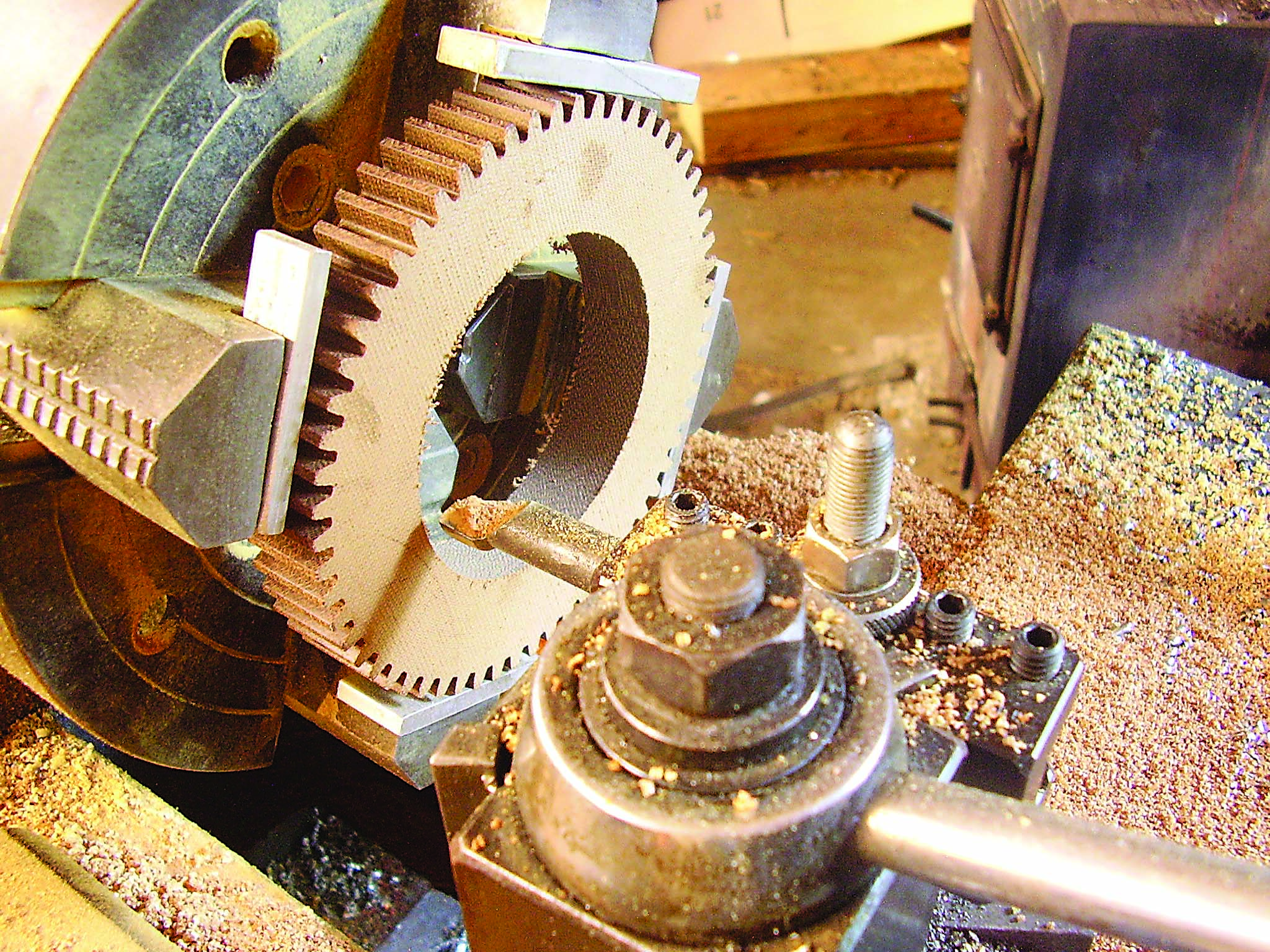
Pieces of aluminum stock are placed between the chuck jaws and the gear teeth. Image courtesy of B. Taylor
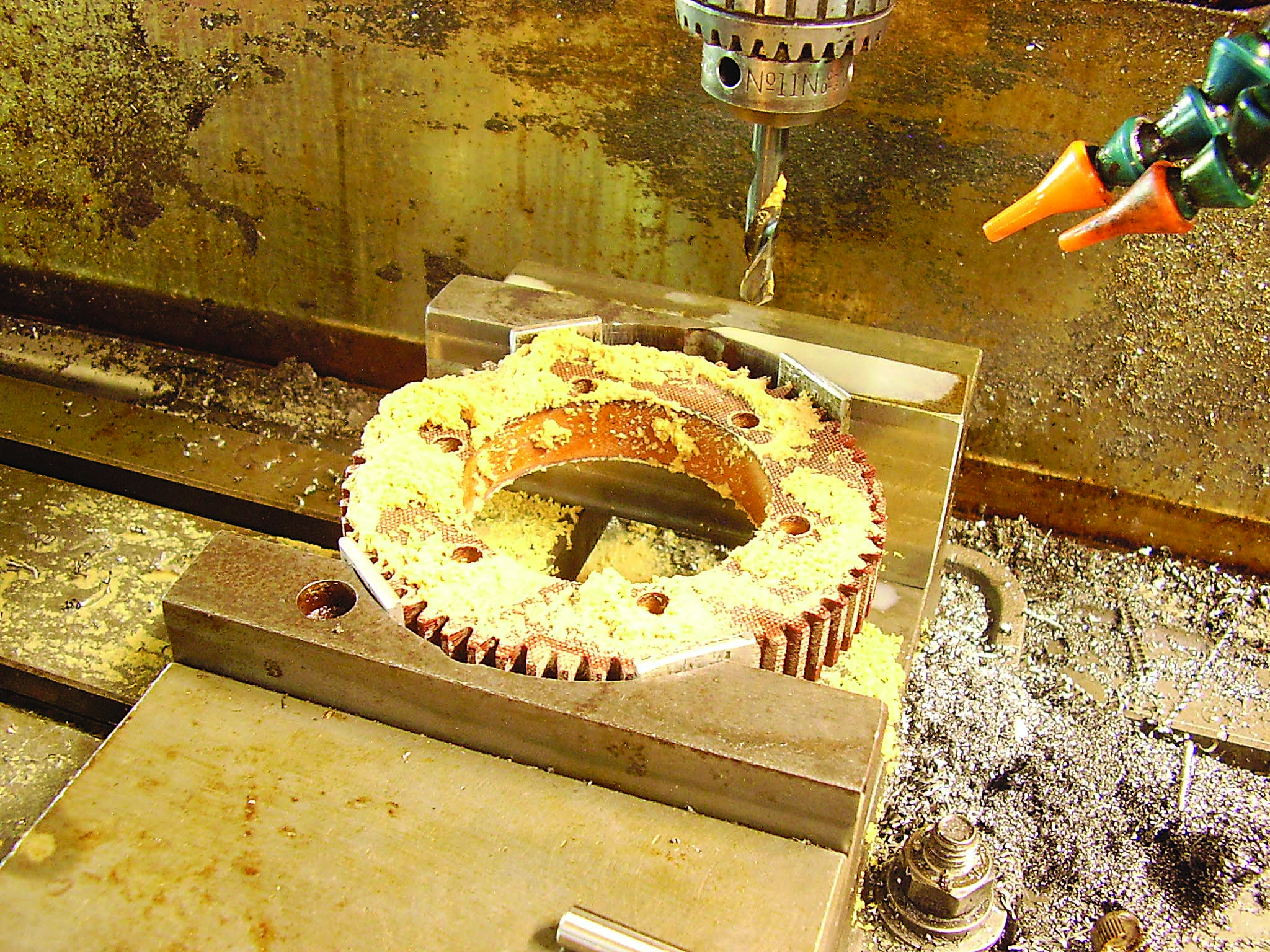
The mill setup is shown. Image courtesy of B. Taylor
Review the print ads from this magazine to continue
This quick advertiser review unlocks the rest of the article and keeps the full-screen reader focused on the ads instead of the page chrome.
Advertisers included in this article experience
Print placements connected to this article
mtseries.com | 800.733.3976
FOUR REGIONS,
ONE MISSION. A powerful face-to-face event series, where people and advanced manufacturing technology unite. REGISTER TODAY. Feb. 21-23, 2023 May 16-18, 2023 Oct. 24-26, 2023 Nov. 7-9, 2023 Houston, TX West Springfield, MA Long Beach, CA Greenville, SC produced by.
FOUR REGIONS, ONE MISSION. A powerful face-to-face event series, where people and advanced manufacturing technology unite. REGISTER TODAY. Feb. 21-23, 2023 May 16-18, 2023 Oct. 24-26, 2023 Nov. 7-9, 2023 Houston, TX West Springfield, MA Long Beach, CA Greenville, SC mtseries.com | 800.733.3976 produced by
Visit mtseries.com | 800.733.3976 View this placement in the issue recordPrint ads from this magazine
ONE MISSION. A powerful face-to-face event series, where people and advanced manufacturing technology unite. REGISTER TODAY. Feb. 21-23, 2023 May 16-18, 2023 Oct. 24-26, 2023 Nov. 7-9, 2023 Houston, TX West Springfield, MA Long Beach, CA Greenville, SC produced by.
FOUR REGIONS, ONE MISSION. A powerful face-to-face event series, where people and advanced manufacturing technology unite. REGISTER TODAY. Feb. 21-23, 2023 May 16-18, 2023 Oct. 24-26, 2023 Nov. 7-9, 2023 Houston, TX West Springfield, MA Long Beach, CA Greenville, SC mtseries.com | 800.733.3976 produced by
Continue reading
September 2023
After centering on the 0.75″ bore, I use a carbide boring tool to make the 3″ feature. I like brazed-carbide boring bars because I can make a very sharp edge and set the tool with a positive rake angle. Due to the low modulus, the material will deflect under the edge if it is not sharp enough. When taking a heavy cut, too much material will be removed. With a light cut, too little material will be removed. If you have fussy features, sharpness and a positive rake matter. I cut this bore at 270 sfm or slower.
The material is abrasive and rapidly wears cutting edges. Since the part is clamped lightly in the chuck, I take light cuts, 0.08″ on diameter per pass, until the bore is 0.02″ or so undersized. Then I check the cutting edge. I dress it with a diamond file if needed and then hit the finished size. Hitting the mark is the art of a machinist.
This material does not make curly chips; it crumbles when cut and makes toxic dust that’s not a good idea to breathe. So if you want to live for a while, take care. I am 75 and don’t plan on checking out soon, so I use a dust mask when doing this lathe work.
The bolt circle is drilled on a CNC milling machine in the usual way. Figure 2 shows the mill setup. Be careful because 6″ milling vises can generate a lot of clamping force. I find the center with an indicator. If I make more than one part at a time, I check the center on each one. The bolt hole size is 0.3125″. I use a high-speed steel, screw-machine-length drill with a peck drilling cycle and Rustlick water-based flood coolant. The coolant takes care of the dust.
Holes are drilled at 700 rpm and a feed rate of 3 ipm. This produces a nice hole with clean edges and no frayed fiber. The combination of abrasive material with a low modulus causes the holes to drill undersized. I use a 0.315″ drill and take care to keep the edges sharp. The finished holes are good at 0.31″ to 0.314″. I check the hole size with gauge pins. A duller drill drills a smaller hole, which clamps on the side of the drill. A little care prevents that. If I made a lot of these parts, I would go to carbide drills, but that would be a whole different story. Like I have said in the past, high production is not my game.
Related Reading
- Related guide: Cutting Force Resources.
- Related guide: Workholding Resources.
Glossary terms in this article
Related



Subscribers can use MFGAxis notes, saves and discussion tools with their innoNET account.


