Calculated Forces When Turning: Quick Guide
Turning force calculations help estimate tangential, feed, and radial loads so shops can judge rigidity, horsepower, and chatter risk before dialing in the cut.
Quick take: Turning force estimates are most useful when they help a shop decide whether a setup has enough rigidity, spindle power, and process margin before chatter or edge failure appears. This page is strongest when it is paired with cutting-equation and thermal-growth references, not used in isolation.
Related references: Understanding Cutting Equations, Coefficient of Linear Thermal Expansion: Machining Guide, and Comprehensive Threading Calculators.
Using a new calculation for determining cutting force components and power when turning.
All images courtesy Kennametal
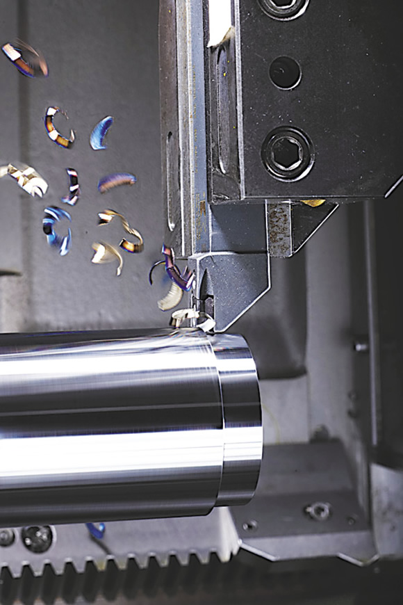
The cutting force when turning is a resultant force that combines tangential, feed and radial force components. These force components can be measured with a three-component force dynamometer. Metalcutting professionals consider Kistler dynamometers the most accurate.
Of the three cutting force components, the tangential force (FZ) is the greatest, the feed force (FY) is less in magnitude and the radial force (FX) is the least in magnitude. As a rule of thumb, the following relationships are used, but it is not a good practice because the results are not as accurate as they could be: FY = 0.50FZ and FX = 0.25FZ.
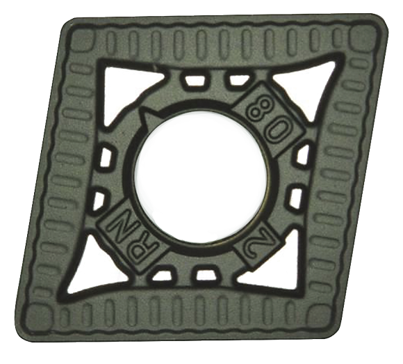
A Kennametal CNMG 120408 RN insert was applied for the roughing test.
On Oct. 25, 2012, Kennametal conducted lab tests at its facility in Fürth, Germany, turning 218-HB alloy steel AISI 4140 (DIN 1.7225 42CrMo4), with the following indexable inserts (ISO specification is in the metric system):
• CNMG 120408 RN for roughing, carbide grade is KCP10;
• CNMG 120408 MN for semifinishing, carbide grade is KCP10; and
• CNMG 120408 FP for finishing, carbide grade is KCP10.
A Boehringer VDF315C CNC lathe and a Kistler quartz-crystal, three-component toolholder dynamometer, type Z15814, were used for the lab tests. The lathe has 80kW (107 hp) of power, 1,400 Nm (1,032 ft.-lbs.) of torque and a VDI 60 turret. The cutting force components (FX, FY and FZ) were recorded (Charts 1, 2 and 3 for roughing below) and tabulated (Tables 1, 2 and 3 below).
The ratios of the feed force to tangential force and the radial force to tangential force are (Table 1):
Test No. 1: FY ÷ FZ = 2,309.42 ÷ 5,358.77 = 0.43; FY = 0.43FZ; FX ÷ FZ = 887.13 ÷ 5358.77 = 0.17; FX = 0.17FZ
Test No. 2: FY ÷ FZ = 2,219.69 ÷ 5,119.33 = 0.43; FY = 0.43FZ; FX ÷ FZ = 919.39 ÷ 5,119.33 = 0.18; FX = 0.18FZ
Test No. 3: FY ÷ FZ = 2,247.57 ÷ 5,113.66 = 0.44; FY = 0.44FZ; FX ÷ FZ = 958.56 ÷ 5,113.66 = 0.19; FX = 0.19FZ
These ratios are 14 to 32 percent lower than those defined by the rule of thumb.
Similar ratios for the cutting force components are (Table 2):
Test No. 1: FY ÷ FZ = 1,479.75 ÷ 3,060.21 = 0.48; FY = 0.48FZ; FX ÷ FZ = 556.12 ÷ 3,060.21 = 0.18; FX = 0.18FZ
Test No. 2: FY ÷ FZ = 1,482.56 ÷ 3,038.97 = 0.49; FY = 0.49FZ; FX ÷ FZ = 576.00 ÷ 3,038.97 = 0.19; FX = 0.19FZ
Test No. 3: FY ÷ FZ = 1,507.77 ÷ 3,063.95 = 0.49; FY = 0.49FZ; FX ÷ FZ = 600.88 ÷ 3,063.95 = 0.20; FX = 0.20FZ
These ratios are 4 to 28 percent lower than those defined by the rule of thumb.
The ratios of the cutting force components are (Table 3):
Test No. 1: FY ÷ FZ = 491.08 ÷ 957.37 = 0.51; FY = 0.51FZ; FX ÷ FZ = 234.86 ÷ 957.37 = 0.25; FX = 0.25FZ
Test No. 2: FY ÷ FZ = 483.72 ÷ 941.74 = 0.51; FY = 0.51FZ; FX ÷ FZ = 236.17 ÷ 941.74 = 0.25; FX = 0.25FZ
Test No. 3: FY ÷ FZ = 496.01 ÷ 957.27 = 0.52; FY = 0.52FZ; FX ÷ FZ = 240.11 ÷ 957.27 = 0.25; FX = 0.25FZ
These ratios are similar to those defined by the rule of thumb.
As shown in Tables 1, 2 and 3, the formula developed by Edmund Isakov provides 96.1 to 99.0 percent accuracy when calculating tangential force. Such accuracy satisfies engineering requirements for metalcutting.
The method of calculating power requirements using tangential force (FZC) and cutting speed (VC) is more accurate than the conventional, rule-of-thumb method, which is based on the unit power values (UP) and the metal-removal rates. A comparison of these two methods of calculation illustrates the difference.
Power Requirements
Calculating the power requirement P using FZC and VC is the advanced method. As an example, the calculations are performed using cutting parameters shown in Table 1 for roughing.
Review the print ads from this magazine to continue
This quick advertiser review unlocks the rest of the article and keeps the full-screen reader focused on the ads instead of the page chrome.

MFGAxis Discussion