As early as the 1980s, master moldmaker Len Graham has been trying to figure out how to automate moldmaking. His brainchild, the “megacell” in the medical containers and closures division of Rexam Mold Manufacturing, Buffalo Grove, Ill., is a proving ground for new automation techniques in an industry previously considered impossible to automate.
Berry Plastics Corp., Evansville, Ind., purchased Rexam in 2014, but Graham’s production line continues to operate, with Graham serving as business unit leader. By using a robotic arm on a track to move parts from one section of the process to another and a standardized, palletized tooling ball to provide a fixed reference point for the CAD/CAM software controlling each machine, he’s already accomplished what others told him was impossible … and he’s not done yet.

The robot and part-management carousels on rail No. 1 of Rexam's manufacturing megacell.
CTE: How did you come up with the idea to automate moldmaking?
Graham: I’ve had these ideas rolling around in my head since the ’80s. People used to call me a lunatic, telling me it’s impossible to automate moldmaking because it’s a discipline that takes 20 years to get any good at. But from the time I was 16 years old, I realized that even though every cavity is different, at the end of the day, they’re either round or square. You’re either grinding it one way or another. Why can’t a robot do that?
CTE: What is the principle behind the tooling ball?
Graham: Every tooling ball is exactly 21/2" from the base to the centerline of the ball. That way, all you have to do is have the computer measure the distance between the center of the ball and the surface of the part, and you know exactly how much you have to grind at any given point. The measurements aren’t relative to the part; they 're relative to the constant location of the centerline.
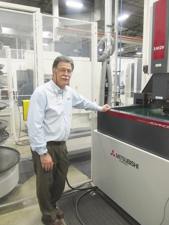
Len Graham, business unit leader at Rexam Mold Manufacturing, with the Mitsubishi EA12V sinker EDM, part of the megacell's first rail.
CTE: How does the megacell work?
Graham: Ultimately, the part is going to be moving back and forth between two rails using a carousel system, with the robot on one rail dropping the part into the carousel and the other picking it up, moving it back and forth until the process is completed. Both robots need to know which machine is open at all times and what stage of machining each part is at. Some machining processes take longer than others and you don’t want production to halt while you’re waiting for an operation to finish, so you need to have things set up in a way that the robot can say OK, let’s do other stuff while waiting for this door to open, then come back when it does. At this point, we’re working out the kinks with rail No. 1, which has two sinker EDMs and a couple of milling centers. That rail is where we need to make sure we’ve perfected the synergy and communication between machines, making sure everything works together, really refining the process, because rail No. 2 is where we’re going to start introducing grinding, turning, spinning and jig grinding.
CTE: What are some challenges you’ve faced developing the megacell?
Graham: Robots have been in machining forever, and they work pretty well when you’re doing a bunch of stuff that’s the same every time. Molds aren’t the same every time, so we needed to develop a customized system. Frankly, when we started, technology really hadn’t caught up with the concept. Now we use SolidWorks for engineering and Delcam to drive the machinery and the good news is those companies see the need for what we’re doing and are starting to catch up. Another challenge is that when I moved here, the company was on SolidWorks, and we brought in Delcam about 2 years ago to provide cutting software and it’s been agony—they really didn’t understand what was needed to make this whole thing work right.
Editor’s Note: The original copy that appeared in this section was incorrect. The correct information is as follows:
Delcam was acquired in February 2014 by Autodesk Inc., San Rafael, Calif. The Delcam office in Rockford, Ill., was added to the Delcam organization through the acquisition of its long-standing reseller, CADCAM Systems, before Delcam was acquired by Autodesk. Representatives from Delcam worked with Rexam to resolve software issues within the automation cell.
CTE: Robots aside, how does your process differ from a typical moldmaking operation?
Graham: Moldmakers are very protective of their process. They like to be the one doing the planning and fixing all the way through the process. But why would you do that if you can make sure it was right before it even comes out of the chute, so there’s nothing to fix? If you give 10 moldmakers the same design, you’ll wind up with 10 different moldmaking processes. That doesn’t work with automation, so our moldmakers have to be part of the design meetings to ensure every process is performed exactly the same way every time. The only thing the designers do on their own is come up with a concept; once we have the idea, the moldmakers collaborate with everyone else from the start to figure out the best way to bring that design into the real world. CTE
Related Glossary Terms
- centers
centers
Cone-shaped pins that support a workpiece by one or two ends during machining. The centers fit into holes drilled in the workpiece ends. Centers that turn with the workpiece are called “live” centers; those that do not are called “dead” centers.
- electrical-discharge machining ( EDM)
electrical-discharge machining ( EDM)
Process that vaporizes conductive materials by controlled application of pulsed electrical current that flows between a workpiece and electrode (tool) in a dielectric fluid. Permits machining shapes to tight accuracies without the internal stresses conventional machining often generates. Useful in diemaking.
- gang cutting ( milling)
gang cutting ( milling)
Machining with several cutters mounted on a single arbor, generally for simultaneous cutting.
- grinding
grinding
Machining operation in which material is removed from the workpiece by a powered abrasive wheel, stone, belt, paste, sheet, compound, slurry, etc. Takes various forms: surface grinding (creates flat and/or squared surfaces); cylindrical grinding (for external cylindrical and tapered shapes, fillets, undercuts, etc.); centerless grinding; chamfering; thread and form grinding; tool and cutter grinding; offhand grinding; lapping and polishing (grinding with extremely fine grits to create ultrasmooth surfaces); honing; and disc grinding.
- jig
jig
Tooling usually considered to be a stationary apparatus. A jig assists in the assembly or manufacture of a part or device. It holds the workpiece while guiding the cutting tool with a bushing. A jig used in subassembly or final assembly might provide assembly aids such as alignments and adjustments. See fixture.
- milling
milling
Machining operation in which metal or other material is removed by applying power to a rotating cutter. In vertical milling, the cutting tool is mounted vertically on the spindle. In horizontal milling, the cutting tool is mounted horizontally, either directly on the spindle or on an arbor. Horizontal milling is further broken down into conventional milling, where the cutter rotates opposite the direction of feed, or “up” into the workpiece; and climb milling, where the cutter rotates in the direction of feed, or “down” into the workpiece. Milling operations include plane or surface milling, endmilling, facemilling, angle milling, form milling and profiling.
- turning
turning
Workpiece is held in a chuck, mounted on a face plate or secured between centers and rotated while a cutting tool, normally a single-point tool, is fed into it along its periphery or across its end or face. Takes the form of straight turning (cutting along the periphery of the workpiece); taper turning (creating a taper); step turning (turning different-size diameters on the same work); chamfering (beveling an edge or shoulder); facing (cutting on an end); turning threads (usually external but can be internal); roughing (high-volume metal removal); and finishing (final light cuts). Performed on lathes, turning centers, chucking machines, automatic screw machines and similar machines.
Author

Evan Jones Thorne, who served as associate editor of Cutting Tool Engineering magazine through February 2017, holds a bachelor’s degree in English and communications from Northern Illinois University. Evan joined Cutting Tool Engineering in October 2013.