An eye for wear
An eye for wear
A machine vision system for inspecting cutting tool wear.
Process monitoring of milling and turning operations is critical to optimizing part quality and costs. Of the process parameters that cutting tool monitoring methods focus on, such as cutting forces, temperature and tool wear, the latter is generally the most relevant because it has a direct impact on final part quality, machine tool performance and tool life, according to researchers at the Laboratory for Machine Tools and Production Engineering of RWTH Aachen University. Of the various types of insert wear, flank wear is the most referenced tool wear parameter in the monitoring process because it enables estimation of tool life and control of the production process, the researchers noted.
In the university's "Machine Vision System for Inspecting Flank Wear on Cutting Tools" paper, published in the ACEEE International Journal on Control System and Instrumentation, authors Robert Schmitt, Yu Cai and Alberto Pavim describe their prototype automated machine vision system that measures tool wear.
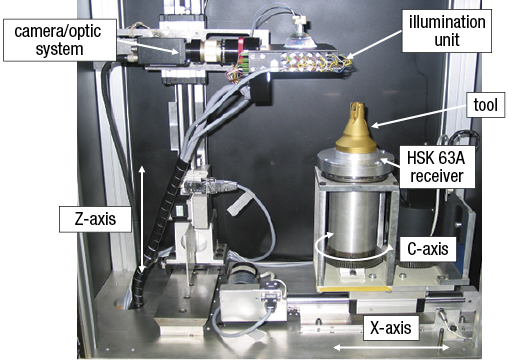
The machine vision prototype for inspecting flank wear on cutting tools.
The system, which measures flank wear next to the production line, consists of three hardware modules: a flexible illumination unit, a camera/optic system and a mechanical system. The illumination unit has three types of lights to provide optimal wear detection and measurement: top light, half-ring light and side lights. The camera is a monochrome CCD (charge-coupled device) camera with an effective sensor size of 752×582 pixels.
The mechanical system has three motorized axes. The Z-axis positions the camera based on tool height, the X-axis drives the cutting tool head into focus based on tool diameter, and the C-axis rotates the tool to position all inserts into focus.
To automate flank wear measurement, the researchers built the system with an image processing chain. The basic image processing tasks are image acquisition, tool-edge detection, wear region highlighting, feature extraction, wear-type classification and wear measurement.
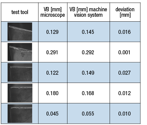
A comparison of test results for measuring the flank wear value (VB) achieved by a microscope and the prototype machine vision system.
Researchers used five worn inserts to evaluate the system and took 10 test images for each insert. They then compared the system's flank wear measurements to manual measurements performed by tool specialists using a microscope. They found the deviation between the automated and manual measurements in flank wear ranged from 0.001mm to 0.027mm, which their analysis indicated was caused by dirt on the inserts in the prototype, and determined the repeatability of automated tool wear measurement was an acceptable 7.5µm.
For more information about RWTH Aachen (Germany) University's Laboratory for Machine Tools and Production Engineering, visit www.wzl.rwth-aachen.de. For a copy of the paper, visit hal.archives-ouvertes.fr/docs/00/74/16/33/PDF/13.pdf. CTE
About the Author: Alan Richter is editor of CTE. He joined the publication in 2000. Contact him at (847) 714-0175 or [email protected].