Finish strong with CAM software
Finish strong with CAM software
Finishing is an active area of CAD/CAM software development that becomes better every year. Discover how it can benefit your operations.
As cutting tool types, shapes and capabilities continue to advance, precision CAM software must keep up to safely optimize cutting performance. Precision tooling coupled with powerful software capabilities offer manufacturers the potential for better part quality and decreased cycle times.
Take a moment to visualize your machining processes. Do you know which have room for improvement?
Most customers look for cycle time improvements on roughing operations. Roughing is where the most benefits can be achieved when implementing a new strategy or trying to cut costs or time. This is also where most timesaving CAM technologies have focused their efforts. But another process is worthy of a closer look: finishing.
Finish is a critical manufacturing component because, in addition to its visual aspects, it affects part quality, performance and material properties. Despite its importance, I find that manufacturers do not often consider finishing an operation that can be improved upon. In fact, many believe that not much can be done. They think that achieving a quality finish takes time, and that's the end of it. This may be the case with traditional finishing operations but not with new tools in CAD/CAM software packages.
In our case, in Mastercam we call it Accelerated Finishing, which uses new cutting-edge geometries from tool manufacturers to decrease cycle time while improving part quality and finish. The software includes these geometries in all three-axis and multi-axis toolpaths via existing toolpaths, not within a new toolpath suite. All paths are familiar to Mastercam users — there's no need to relearn anything. It's just a matter of applying a new tool form and strategy to these existing paths.

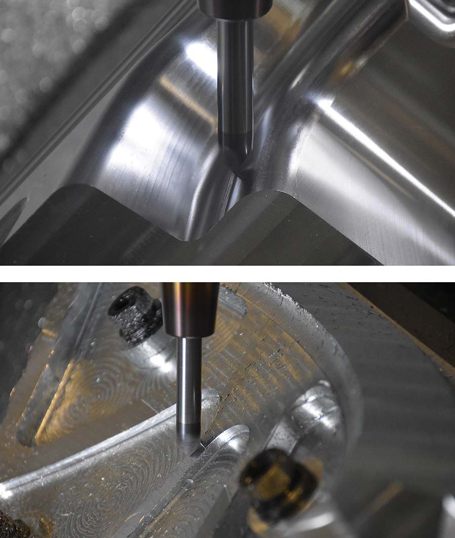
A circle segment endmill delivers a precision finish while reducing machining time. Image courtesy of CNC Software
Finishing is an active area of CAD/CAM software development that becomes better every year regarding how software supports tools, tool geometries, control strategies and tool libraries. The technology was developed in conjunction with innovations in advanced cutting tool shapes, including oval form cutters, barrel mills, taper cutters, lens-shaped cutters and combination lens-barrel form tools.
It's no secret that traditional finishing operations are the most time-consuming of milling operations. Generally, the longer the cycle time, the better the finish. But these new software advancements change all that. For example, one of our customers produces titanium medical implants. By using Accelerated Finishing instead of traditional finishing methods, the company reduced cycle time and accordingly increased tool life. The improvements translated into significant cost savings. The interesting thing here is that this medical device manufacturer was already roughing efficiently but now was able to decrease cycle time on the finishing side.
From a technical perspective, improving surface finish quality is all about reducing cusp height. That is the deviation and looks like little waves on the surface that a tool leaves when it removes material. A smaller cusp height yields a better surface finish. Typically, to reduce cusp height, a larger-diameter tool is needed. This methodology uses a tool of small diameter with a large effective cutting radius on specialty profile. This allows a user to reduce cusp heights while increasing the step-over, thereby increasing surface quality while not forcing the use of a large-diameter tool. The secret to successful use of these tools is maintaining proper tangency of the cutting radius to the surface being cut.
New finishing software supports complex and irregular tool profiles. This strategy is great for machining mold cavities and cores — anything that has a large surface with a low rate of curvature change. Such parts tend to have surfaces that machinists would spend a lot of time on, so the strategy is a good fit.
When the finishing software application is executed correctly, it's a home run. But as with any technology, education is key. One challenge to optimizing benefits is understanding when and where to apply these tools. Some customers see the capability of them and want to apply them to everything, but they have very specific requirements for a given surface. It must be large but cannot have a high rate of change of curvature. Think of a large surface in a mold cavity or mold core — something you'd spend a lot of time on. You now can machine it significantly quicker and obtain a better finish.
These new CAD/CAM finishing advancements are not widely used yet, but they are more popular by the day. A few years ago, only one or two tooling manufacturers made advanced cutting tool shapes. Now these tools are becoming commonplace across the industry.
In our case, this software technology originally stemmed from our partnership with precision cutting tool manufacturer Emuge-Franken USA, the innovator in this realm. Since then, we have worked with many different tool manufacturers that are on the cutting edge of this technology. Early collaboration was key to success. From the beginning, we recognized the importance of educating tool manufacturers and end users on what these new cutting tools did and how to properly apply them. We collaborated with technical staffs on how to utilize the tools within the CAM software and on parts for customers.
If you are looking to improve part quality and cut down on production time and costs, I encourage you to explore your finishing processes. Learn how the latest CAD/CAM software developments in finishing improvements may benefit your operations.


