Finite element analysis in the supply chain
Finite element analysis in the supply chain
As component design optimization tasks flow down the supply chain, finite element analysis programs proliferate.
Finite element analysis (FEA) is about solving the dilemma of the road not taken: You know where you want to go but don't know which divergent road will get you there. Suppliers tasked with optimizing a component's design face the same dilemma—and going down the road of a poor design can be costly. FEA software allows you to take infinite roads, but virtually, saving time and material costs.


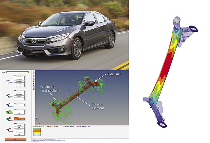
The Gestamp RTB suspension can be found on many makes and models, including the Honda Civic. Altair developed the RTB toolbox interface (bottom). Stress contours for a critical antiphase fatigue load case (right). Images courtesy Honda Motor Co. (top) and Gestamp/Altair.

"Finite element modeling lets you optimize the design of components, taking into account the material that you're using," said Jon Riley, senior vice president of technology at the National Center for Manufacturing Sciences (see "Making Light Work" in the August issue of CTE). "To use an exaggerated example, if you're using titanium, you don't need to make a rivet as thick as you would if you were using nylon. You can ask, 'How do I make the geometry of this part optimally, considering not only the material but also the [material-processing operation] I'm using?' You can optimize the geometric shape of the part for whatever your priority is—for cost, for mass, for performance or all three."
You may be wondering, "What does that have to do with me? I work at a job shop, not an OEM." Not so fast. In the past decade, OEMs in many industries have pushed elements of product and component design optimization onto the supply chain. Aerospace examples include the Boeing 787 and the Lockheed Martin F-35. For that reason, a growing number of job shops are learning to value FEA software, particularly as software developers compete to make it more versatile and easier to use.
"Often, our involvement includes a combination of software and consulting," said Simone Bonino, vice president of marketing of HyperWorks, a suite of computer-aided-engineering software from Altair Engineering Inc., Troy, Mich. "That seems to be a particularly effective strategy for the supply chain, since they are often new to the concept of virtual prototyping and simulation-driven design."
Suspenseful FEA
Altair customer Gestamp, Madrid, Spain, is a global chassis-component supplier for automotive OEMs, with technical centers in the U.K., Spain and Germany, and an R&D center in Troy, Mich. One of its product is a rear twist beam (RTB) suspension system, commonly found in A-, B- and, increasingly, C-class vehicles because of its low manufacturing cost, small package requirement and the acceptable vehicle-handling performance it produces. Gestamp selected Altair to develop a set of custom tools, referred to as "the RTB toolbox," which can be used to generate an initial RTB concept that meets kinematics and compliance requirements and, thereby, eliminates an initial trial-and-error design loop.
The software used the functionality available within Altair's HyperMesh, which manages the generation of complex models. HyperMesh set up shape-design variables for each component in the RTB assembly. Then HyperStudy, a design-exploration tool that automatically creates intelligent design variants, was used to control design-of-experiment studies. These provided a detailed understanding of the sensitivity of each target to input parameters. This was then followed by a final optimization step from which concept surfaces were generated.


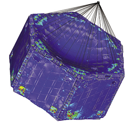
The "Plug-and-Play Satellite" features a modular framework of panels. Image courtesy Siemens PLM Software.

The next stage of the design process was to create a CAD model from the optimized RTB toolbox output. This model served as a baseline for work to meet durability and strength criteria. Durability analysis and prior experience were used to define stress limits for welds in critical areas, such as those between the reinforcer and torsion element. Opposing vertical displacements were applied to the wheel centers of an RTB system to simulate repeated cycles of vehicle cornering. The analysts found that, generally, an increase in roll stiffness reduced the fatigue performance. A combined shape optimization of the reinforcer length and torsion-element gage was created—a solution that minimized mass while respecting durability and roll-stiffness constraints.
"We have found the optimization software to be an asset to our RTB design process," said Andrew Charlesworth, Gestamp design analyst.
Off-the-Shelf Satellite Parts
FEA is also being used in aerospace applications. Satellite-provider SpaceWorks, Scottsdale, Ariz., is helping to develop the next generation of satellite structures for the U.S. Air Force Research Laboratory. Appropriately named "Plug-and-Play Satellite" (PnPSat), each features a modular framework of panels that share an electrical and communication bus that can be assembled into a fully functional and ready-to-launch satellite in a matter of days.
Typically months, and usually years, have been required to design and build a dedicated satellite. With PnPSat, depending upon the mission of the satellite, any number of "off-the-shelf" spacecraft component modules can be plugged into the panels.
A key factor in the utility of a PnP satellite is its lightweight and rigid structural framework that facilitates the easy placement of spacecraft component modules, such as batteries and telescopic imagers. To allow commonality of usage, the framework launches the lightest combination of modules in any desired grouping. Determining the appropriate combination required extensive use of engineering optimization FEA.
To expedite this process, Predictive Engineering Inc., Portland, Ore., was hired as SpaceWorks' FEA specialist. Using Femap FE modeling software with NX Nastran, a program for structural simulation from Siemens PLM Software Inc., Plano, Texas, Predictive Engineering built FE models that allowed SpaceWorks to gain insights into the structural performance of this novel spacecraft structure.


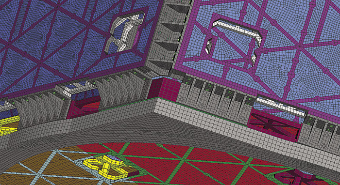
Closeup of the detailed mesh map of the PnPSat structure. Image courtesy Siemens PLM Software.

The PnPSat structure is composed of eight panels that are bolted together. Each panel is made up of two symmetric halves. The panels have thick ribs to provide structural reinforcement with a thin outer skin. If a standard design approach had been used—for example, to simply mesh the geometry with 10-node tetrahedrals—the resultant FE model would have been in the range of tens of millions of nodes and would have been unsolvable.
Predictive Engineering determined that the only practical approach was to mesh the thin skin using plate elements and the thicker ribs with eight-node bricks. Using the advanced meshing techniques in Femap, a completely mapped mesh (bricks and plates) of the PnPSat structure with a node count of approximately 800,000 was produced. Although large by most analysis standards, the FEA results for the structure's normal modes were found to be within 5 percent of experimental results.
"We knew we were pushing the technology of both Femap and NX Nastran with this model, and such tight correlation just confirmed to us that we were on the right track," said George Laird, principal mechanical engineer for Predictive Engineering. "To see such a good correlation on a very complex system model was impressive."
Within weeks, SpaceWorks was able to verify its new design and win accolades from its main client, the U.S. Air Force Research Laboratory.
FEA Overhead
Another aerospace example: When an aircraft-interior manufacturer developed a new bin to provide a roomier cabin with more overhead stowage capacity, the internal turbulence-restraint bracket required a redesign. The prior part had some stress inefficiencies.
The company turned to structural-optimization consultant Smithson Engineering, Crestline, Calif., which used automated topology optimization tools to look at load paths and efficient shapes. FEA software Autodesk Nastran, from Autodesk Inc., San Rafael, Calif., was used to adjust design alternatives.


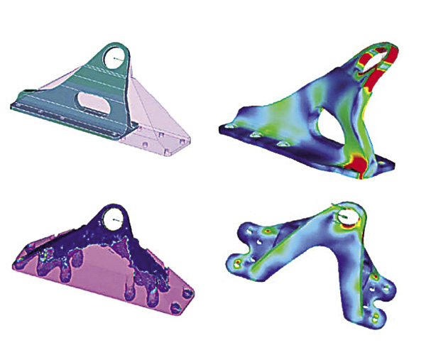
Design evolution of the internal turbulence-restraint bracket. Image courtesy Autodesk.

First, the existing part's strengths and weaknesses were analyzed. The part was machined from 2024 aluminum, and the customer's targeted weight reduction was 50 percent. Although the part experienced minor deformation under the maximum test load, exaggerated deformations showed that the part was more likely to twist than to buckle—it showed much more resistance in the direction of its length. To compensate for this relative twisting susceptibility, the main wall of the part needed to be much thicker than otherwise necessary.
The geometric envelope for the design space was increased. Boundaries only included the load attachment surfaces and the bolt attachment surfaces. The topology was refined several times, with intermediate convergence solution showing that some bolts were not connected and yet not fully removed from the solution.
Based on this work, several design options were considered. The one proposed was a symmetric bracket with four legs that is approximately half the weight of the original bracket, with a reduced part count and the ability to be used on either left- or right-side locations.
"We performed FEA analyses with Autodesk Nastran, using classic iterative material-removal methods, to help the customer reduce the weight," said Tyler Smithson, Smithson Engineering principal engineer, "thus reducing the operating cost and providing additional 'green' benefits."

Contributors
Altair Engineering Inc.
(248) 614-2400
www.altair.com
Autodesk Inc.
(415) 507-5000
www.autodesk.com
Siemens PLM Software Inc.
(800) 498-5351
www.plm.automation.siemens.com


