Get on a roll with centerless grinding
Get on a roll with grinding wheel. This method allo…" title="Grinding operation in which the workpiece rests on a knife-edge support, rotates through contact with a regulating or feed wheel and is ground by a grinding wheel. This method allo…" aria-label="Glossary: centerless grinding">centerless grinding
The operation can produce a countless variety of components.
grinding wheel. This method allo…" title="Grinding operation in which the workpiece rests on a knife-edge support, rotates through contact with a regulating or feed wheel and is ground by a grinding wheel. This method allo…" aria-label="Glossary: centerless grinding">Centerless grinding was developed in the early 1900s to improve the manufacture of rollers for roller bearings used in bicycles. Today, the process is used by automotive manufacturers, medical device manufacturers and small job shops to produce a countless variety of components.
The operation has a combination of qualities not found with any other machine tool. The process is simple in appearance, exceptionally productive, very repeatable and capable of holding tight tolerances.
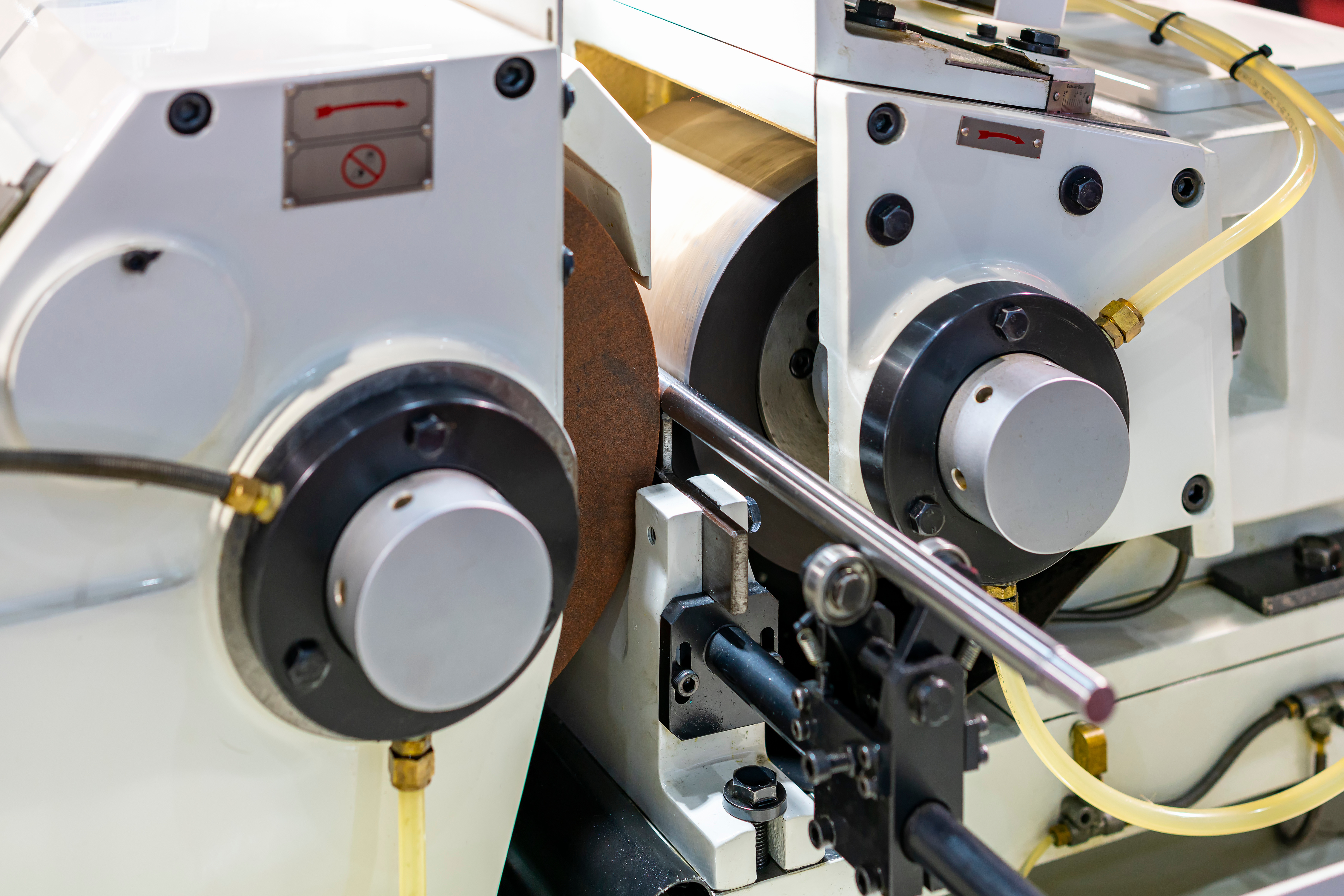
Centerless grinding looks deceptively easy. The grinder is constructed with a grinding wheel mounted in a stationary housing on one side of the machine with a work rest and regulating wheel, also known as a reg wheel, opposite the grinding wheel. The reg wheel and tool rest are mounted on a two-slide arrangement in which the work rest is mounted to the lower slide and the reg wheel is mounted to the upper slide. This arrangement allows the reg wheel to move relative to the work rest, which is primarily for setting the height of the workpiece relative to the grinding wheel. The lower slide carries the work rest and reg wheel to the grinding wheel and controls the depth of cut and diameter of the workpiece.
Although the arrangement of these primary components is simple, the effect is significant. Centerless grinding is not subject to errors caused by a part that is out of round or bent. Because the work rest is positioned 90 degrees to the wheels, grinding plane geometric imperfections do not produce irregular motion in the cut plane. This relationship makes centerless grinding the most efficient process for creating very round parts.
Supporting the entire working area with the rest prevents deflection that would occur in other kinds of grinding operations. Therefore, centerless grinding is ideal for parts that are long and slender. Because lengthy, flimsy workpieces are manufactured easily with centerless grinding, the medical industry extensively uses the process to make things like catheters, which have very tight diameter tolerances and would be impossible to create on other types of machine tools. Since the work is well supported and the depth of cut can be as little as a few millionths of an inch, centerless grinding is perfect for thin-walled tubular parts or really brittle workpieces. An extreme example is companies that produce glass tubes with diameter tolerances in the 0.00254 mm (0.0001") range using centerless grinders.

A centerless grinder is constructed with a grinding wheel mounted in a stationary housing on one side of the machine with a work rest and regulating wheel opposite the grinding wheel. Image courtesy of Cutting Tool Engineering
Slide travel, wheel arrangements and the overall size of a centerless grinder limit the maximum working diameter of a workpiece. However, the unique configuration of the wheels and rest allows parts to be fed through the machine from entry to exit without interruption, aka through-feed grinding. So there is no limit to the length of a workpiece. The most common type of centerless grinding is through-feed grinding. Reg wheels are dressed to a slightly concave, tapered shape, which pulls the workpiece through the machine. Therefore, the entire grinding process happens without movement of the slideways. The part enters on one side and is fed across the grinding wheel and exits on the other side. Cutting speed (feed rate) and size are controlled by the shape of the reg wheel.
When set up for through-feed grinding, a centerless grinder requires very little adjustment. Once dialed in, through-feed grinding is exceptionally repeatable, and a well-developed through-grinding process can produce large quantities of close-tolerance parts with no interruption. With a good setup, the only time that the process is interrupted is for wheel dressing. Like all grinding operations, the wheel will wear and need dressing to restore the shape and expose new abrasive grains. Since dressing changes the diameter of the wheel, slide adjustments are required to maintain the diameter of the workpiece. Wheel life on a centerless grinder is typically much greater than other grinding operations, so dressing and subsequent adjustments are infrequent.
Because the process is so stable, centerless grinding is automated easily. High-volume manufacturers outfit the machines with robots, pick-and-place automation and vibratory feeders, eliminating the need for a person to load the machine. It is also common to find automatic gauging attached to the machines, which creates a feedback loop with the control allowing in-process dimensional adjustments and wheel dressing. Automation combined with the very stable grinding process forms an extremely productive system.
Centerless grinding has many obvious applications for high-volume manufacturing or situations in which materials are difficult to machine. The process also has applications at low-volume shops.
At a previous employer, we were making parts from stainless steel tubes, and the 50.8 mm (2") dia. needed to be reduced by 0.8128 mm (0.032") because we could not buy metric tubes. Our tubes had to be 50 mm (1.968"). We were trying to turn the parts, which were 1,219.2 mm (48") long, and struggled with chatter. The result was an ugly finish that required a lot of time polishing to correct. We eventually began sending the raw material to a shop that specialized in centerless grinding and decreased the diameter of the tubes, eliminating our turning operations.
In another case, we were making shafts that were simple cylinders. There were no features on the outer diameter except for a few milled flats. It was the same diameter from end to end. After machining, the shaft was hardened to 62 HRC, and the final finish required grinding. We tried several ways of completing the work on our OD grinder but never could eliminate the mismatched lines and taper caused by grinding a cylinder in multiple setups. As you probably can guess, this was an ideal application for centerless grinding. As in the other example, we sent the shafts to the grind shop, which saved money for us. Later, like with the stainless steel tubes, we started sending the raw material to the grind shop and eliminated the turning operations for this part as well.
Centerless grinding is efficient and perfect for high-volume manufacturing. The process is stable, accurate, economical and many times the only method that can do the job. Although its roots are in high production, centerless grinding can benefit low-volume manufacturers too thanks to the same attributes.


